
Optical fiber connecting method

A connection method and optical fiber technology, applied in the coupling of optical waveguide, light guide, optics, etc., can solve the problems of lowering the laser threshold, abnormally sensitive optical signal isolation, laser oscillation, etc., and achieve the effect of ensuring the quality of welding

Inactive Publication Date: 2013-02-27
TSINGHUA UNIV
View PDF3 Cites 13 Cited by
  • Summary
  • Abstract
  • Description
  • Claims
  • Application Information

AI Technical Summary

Problems solved by technology

In order to achieve low-loss high-quality fusion splicing, it is generally necessary to treat the end face of the optical fiber to be vertical and flat, but this also introduces echo reflection at the melting point and various adverse effects it brings
[0004] For example, as an ideal broadband light source for fiber optic gyroscopes, optical tomography, medical diagnosis, and many other systems such as fiber optic sensing, fiber detection, and WDM optical communication, superfluorescent fiber light sources can directly achieve spontaneous emission by pumping high energy into doped fibers. Radiation amplification to obtain fiber optic superfluorescence seed source, but due to the existence of discrete optical elements or optical feedback at the melting point in this system, it is very easy for the gain to be greater than the loss in the cavity formed by the gain fiber to self-oscillate (P.Wang, J.K.Sahu, and W.A.Clarkson, "110W double-ended ytterbium-dopedber super-fluorescent source with M2=1.6", Opt.Lett.31, 3116-3118 (2006); Qirong Xiao, Ping Yan, Yaping Wang, Jinping Hao, and Mali Gong, "High-power all-fiber super-fluorescent source with fused angle-polishedside-pumping configuration", Appl.Opt., 50, 1164-1169(2011)), is extremely sensitive to the isolation of optical signals, and the output power is therefore severely restricted
But even if it is an all-fiber structure, the return loss at each melting point cannot be avoided. This part of the feedback will cause laser oscillation, reduce the laser threshold, and limit the maximum output power of ASE. It is necessary to introduce an optical isolator, which increases loss and cost. (Cao Yi, Liu Jiang, Wang Ke, Wang Pu, "All-Fiber Hundred-Watt-Level Broadband Ytterbium-Doped Double-Cladding Fiber Superfluorescent Source", Chin.J.Lasers., 39, 0802008(2012))

Method used


Image

  • Optical fiber connecting method
  • Optical fiber connecting method
  • Optical fiber connecting method

Examples


Embodiment 1

[0036] like figure 2 As shown, this example is an embodiment in which the method of the present invention is used in an optical fiber superfluorescent seed source. The broadband superfluorescent seed source is composed of a semiconductor laser 9 , a (n+1)x1 pump beam combiner 10 , an angle fusion point 11 , and a Yb-doped double-clad fiber 12 . The semiconductor laser 9 is used as a pumping source, and its tail fiber is connected to the input fiber of the (n+1)x1 pumping beam combiner 10, and the output end of the (n+1)x1 pumping beam combiner 10 is welded at an angle Connect with one end of the Yb-doped double-clad fiber 12, 11 is the angle fusion welding point, the other end of the Yb-doped double-clad fiber 12 and the signal end of the (n+1)x1 pumping beam combiner 10 are all cut into The 8-degree angle serves as the output end of the fiber optic superfluorescence. Because the connection between the (n+1)x1 pumping beam combiner 10 and the Yb-doped double-clad fiber 12 i...

Embodiment 2

[0038] like image 3 As shown, this example is an embodiment in which the method of the present invention is used in an optical fiber superfluorescent seed source and its amplifier. The main oscillation power amplification MOPA structure adopted mainly includes two parts: a broadband superfluorescent seed source and an optical fiber power amplifier. The broadband superfluorescent seed source consists of a first semiconductor laser 9, a first (n+1)x1 pump beam combiner 10, a first angle fusion point 11, a first Yb-doped double-clad fiber 12 and a pump light leaker 13 constitute. Wherein the first semiconductor laser 9 is used as a pumping source, and its tail fiber is connected to the input fiber of the first (n+1)x1 pumping beam combiner 10, and the output of the first (n+1)x1 pumping beam combiner 10 The end is connected with an end of the first Yb-doped double-clad optical fiber 12 by angle fusion welding, 11 is the first angle fusion welding point, and the other end of the...


PUM


Abstract

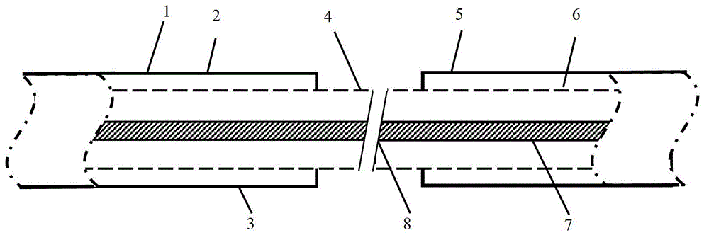
The invention provides an optical fiber connecting method comprising the following steps of: respectively removing small sections of coating layer on the respective ends to be connected of two sections of optical fibers to be connected to expose optical fiber cladding layers, and cutting end surfaces at the same inclined angle; placing the cut inclined end surfaces of the optical fibers to be connected in a way of clinging to complementing positions and welding the cut inclined end surfaces of the optical fibers to be connected together to finish angle welding of the optical fibers to be connected. The optical fiber connected by using the connecting method provided by the invention has the advantages that the optical feedback surface at a melting point is an inclined surface, so that reflected light returning along the original path is reduced, the optical feedback surface at the melting point hardly forms a laser resonant cavity together with other optical feedback surfaces in a system, oscillation of parasitic laser initiated by optical feedback of a low melting point can be reduced, the output power of ASE (airborne support equipment) is increased, the introduction of an optical isolator is even avoided, the loss and the cost are reduced, and the optical fiber connecting method is effectively applied to systems such as optical fiber laser and wideband superfluorescent optical fiber light source.

Description

technical field [0001] The invention relates to the technical field of optical fiber lasers, in particular to an optical fiber connection method. Background technique [0002] In various systems containing optical fibers, it is almost inevitable to have a low-loss, high-quality connection point between fibers, but due to the change in the refractive index of the fiber material on both sides of the connection point, formed at the connection point In the optical feedback surface, the feedback light may easily cause damage to the device or reduce the performance of the system in many cases. Optical fiber connectors widely used in communication systems, according to the different contact methods of pigtail end faces, there are two types: PC and APC. The coupling surface of the former is vertical, and the influence of echo reflection cannot be ignored in many cases; the latter The coupling surface of the connector is generally an end face with an angle of 8 degrees, so the echo ...

Claims


Application Information

Patent Timeline
Patent Type & Authority Applications(China)
IPC IPC(8): G02B6/245G02B6/25G02B6/255
Inventor 闫平肖起榕李丹巩马理张海涛
Owner TSINGHUA UNIV
Learn More