High-energy electron charging current testing system

A technology of high-energy electronics and charging current, applied in the direction of measuring current/voltage, measuring devices, measuring electrical variables, etc., can solve the problems of radiation damage sensitivity, semiconductor material performance deterioration, and unusability, etc., to achieve good radiation resistance, Simple structure, easy to achieve effect

Active Publication Date: 2013-03-13
NO 510 INST THE FIFTH RES INST OFCHINA AEROSPAE SCI & TECH
View PDF3 Cites 0 Cited by
  • Summary
  • Abstract
  • Description
  • Claims
  • Application Information

AI Technical Summary

Problems solved by technology

[0004] The disadvantage of this method is that the physical structure and electronic system of the semiconductor detector are complex, and the processing technology is not easy to realize. At the same time, the semiconductor material is sensitive to radiation damage. Under the irradiation of high-energy electrons, the performance of the semiconductor material will deteriorate after irradiation. Cause the detector test results to be abnormal, or even unusable

Method used


Image

  • High-energy electron charging current testing system

Examples


Embodiment Construction

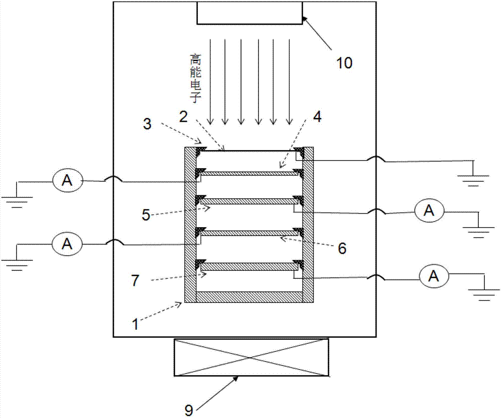
[0021] See attached figure 1 , a high-energy electron charging current testing system, which includes: a vacuum system 9, an electron accelerator 10 and an electron shielding device placed in the vacuum system 9, and an electrometer placed outside the vacuum system 9;

[0022] The electron accelerator 10 is placed directly against the upper end of the electron shielding device;

[0023] The electronic shielding device includes: metal shell 1, insulating ring 3, shielding layer 2, test pole A4, test pole B5, test pole C6 and test pole D7; the inside of the metal shell is composed of test pole A4, test pole B5, test pole C6 and The test pole D7 is layered sequentially from top to bottom. The top of the metal casing is sealed by the shielding layer 2. Insulation is provided at the connection between the metal casing and the shielding layer 2, test pole A4, test pole B5, test pole C6, and test pole D7. Ring 3; test pole A4, test pole B5, test pole C6 and test pole D7 are respecti...


PUM


Abstract

The invention belongs to the technical field of vacuum measurement, and particularly relates to a high-energy electron charging current testing system which comprises a vacuum system (9), an electron accelerator (10), an electronic shielding device and an electrometer, wherein the electron accelerator (10) and the electronic shielding device are arranged in the vacuum system (9); the electrometer is arranged outside the vacuum system (9); the electronic shielding device comprises four testing poles; the electron accelerator (10) is just facing to the upper end of the electronic shielding device; high-energy electron energy and beam current density can be selected within the energy range of 0.2-2MeV; and the electron accelerator (10) is started, and the electrometer is used for testing the current values of the testing poles. The high-energy electron charging current testing system can be used for testing the charging current values of all the testing poles under the condition of high-energy electron irradiation by utilizing a structure of multiple layers of testing poles with different thicknesses, and has the characteristics of being simple in structure, convenient to implement and the like; therefore, the test results of high-energy electron charging current with different energy can be obtained.

Description

technical field [0001] The invention belongs to the technical field of vacuum measurement, and in particular relates to a testing system for high-energy electronic charging current. Background technique [0002] In medium earth orbit and geosynchronous orbit, the flux density of high-energy electrons in space is relatively large. High-energy electrons will pass through the shielding layer of the satellite, deposit and discharge on the surface of the spacecraft's internal materials or inside the dielectric material, causing serious internal charging effects in the spacecraft. Because the internal charging effect usually occurs inside the spacecraft, it will cause abnormal circuit operation or even damage its electronic system, which seriously threatens the safe operation of the spacecraft in orbit. [0003] The charging current of high-energy electrons is an important factor affecting the electrification effect in the spacecraft. At present, semiconductor detectors are main...

Claims


Application Information

Patent Timeline
Patent Type & Authority Applications(China)
IPC IPC(8): G01R19/00G01R1/18
Inventor 陈益峰秦晓刚李得天杨生胜柳青汤道坦王俊史亮李存惠
Owner NO 510 INST THE FIFTH RES INST OFCHINA AEROSPAE SCI & TECH
Why Eureka
Try Eureka