Workmanship of indoor microscopic oil displacement model

A production process and oil displacement technology, which is applied in the fields of production fluid, wellbore/well components, earthwork drilling and production, etc. It can solve problems such as difficult to accurately simulate pore diameter, glass sintering, and microscopic models difficult to be smaller than 20 μm

Inactive Publication Date: 2013-03-20
SOUTHWEST PETROLEUM UNIV
View PDF4 Cites 17 Cited by
  • Summary
  • Abstract
  • Description
  • Claims
  • Application Information

AI Technical Summary

Problems solved by technology

The pore network model is to use photolithography technology to etch the pore pattern of porous media on the glass. As early as the mid-1980s, the Chinese Institute of Scientific Percolation Mechanics mastered the photolithography technology to make the pore network model, but due to the photolithography process Due to problems such as photoresist, exposure time, corrosive liquid and glass sintering during sintering, the pore diameter of the microscopic model is difficult to be less than 20 μm, and it is difficult to accurately simulate the pore diameter of medium and low permeability reservoirs

Method used


Image

  • Workmanship of indoor microscopic oil displacement model
  • Workmanship of indoor microscopic oil displacement model
  • Workmanship of indoor microscopic oil displacement model

Examples


Embodiment 1

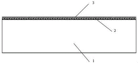
[0021] Embodiment 1: First select a glass substrate that has been polished on both sides, place it in a mixed solution of 70 g of concentrated sulfuric acid and 30 g of hydrogen peroxide, and boil it for 2 hours, then clean it with ultrasonic water for 5 minutes, and then dry the surface of the glass substrate with nitrogen. Place it on a baking sheet and set the temperature at 180°C for 10 minutes. Then spin-coat a layer of tackifier (German AllRESIST AR 300-80) on the glass substrate, place it on a baking sheet, control the temperature at 180°C, bake for 2 minutes, and continue to spin-coat the photoresist on the glass substrate ( Germany AllRESIST AR-P3200), placed on a baking sheet, set the temperature at 98°C, and baked for 10 minutes, such as figure 1 shown.

Embodiment 2

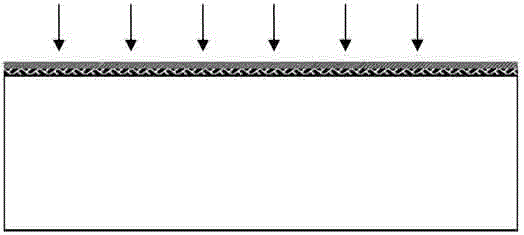
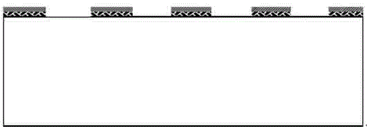
[0022] Example 2: Import the image of the oil reservoir with a pore size of 5 μm into the maskless exposure software, and expose the glass substrate sheet under ultraviolet light for 55 seconds. figure 2 As shown, the glass substrate was then placed in a developer solution (Germany AllRESIST AR 300-26) for 2.5 minutes to develop as image 3 shown. The developed glass substrate was placed on a baking sheet at a temperature of 110° C. and baked for 15 minutes.

Embodiment 3

[0023] Embodiment three: use paraffin to seal other regions except exposed on the glass substrate sheet, be placed in the etching solution that 25g HF, 1.79gNH F and 75g deionized water form, etching time is 180s, as Figure 4 As shown, scrape off the paraffin on the surface of the glass substrate, remove the residual paraffin with kerosene, and clean the photoresist on the surface of the glass substrate with a glue remover (Germany AllRESIST AR 300-72). The mixed solution is boiled for 2h, such as Figure 5 shown.


PUM


Abstract

The invention relates to workmanship of a microscopic oil displacement model used in oilfield chemistry and acid fracturing laboratories to simulate a medium-low permeable oil deposit so as to study the oil displacement process. The invention adopts the technical scheme that the workmanship includes the steps: polishing, washing and blow-drying a glass substrate and then roasting the glass substrate on a glue baking plate; spin coating a layer of tackifier on the glass substrate and then baking on the glue baking plate, so as to form a nano-film; spin coating a layer of photoresist, and baking on the glue baking plate; converting an oil deposit picture into a black and white picture, importing the picture into photoetching software, exposing the glass substrate and then developing in developing liquid, washing, blow-drying, and baking on the glue baking plate; sealing the unexposed part of the glass substrate through paraffin wax, rusting in corrosive liquid, washing, then boiling in sulfuric acid and hydrogen peroxide, washing and blow-drying; tightly pressing the glass substrate to a mica sheet ,and sintering in a muffle furnace; and finally, grinding an access passageway, and putting capillary tubes into the access passageway to make a microscopic oil displacement model for studying the oil displacement process.

Description

technical field [0001] The invention relates to a manufacturing process of an indoor microcosmic oil displacement model used in oil field chemistry laboratories and acid fracturing laboratories to simulate medium and low permeability reservoirs and study oil displacement processes. Background technique [0002] In the existing technology, there are multi-scale problems in the study of the oil displacement process. In oil field production, the research scope is on the scale of kilometers and meters. In the laboratory, the macroscopic physical simulation experiment is generally on the meter scale, while the microscopic simulation experiment It studies the microscopic flow of oil, water and gas in porous media at the micron scale. In the microscopic oil displacement stage, the requirements for the model are to simulate the pore size, pore geometry, and surface mineral composition of the pore system as much as possible, and secondly, the model should have light transmission, so ...

Claims


Application Information

Patent Timeline
Patent Type & Authority Applications(China)
IPC IPC(8): E21B49/00E21B43/27
Inventor 张瑞秦妮彭林周金位叶仲斌
Owner SOUTHWEST PETROLEUM UNIV
Why Eureka
Try Eureka