Coal pyrolysis furnace

A coal pyrolysis and furnace shell technology, applied in the field of coke ovens, can solve problems such as the inability to eliminate environmental pollution, large footprint of CDQ coke towers, and overcapacity of coke, so as to avoid pollution waste and energy loss, and improve oil and gas production capacity. Output, the effect of increasing oil and gas output

Inactive Publication Date: 2014-10-08
SHANXI XINLI ENERGY TECH
View PDF5 Cites 0 Cited by
  • Summary
  • Abstract
  • Description
  • Claims
  • Application Information

AI Technical Summary

Problems solved by technology

[0002] At present, there are many problems in the coke industry, such as severe overcapacity, low industrial concentration, unreasonable industrial layout, low level of comprehensive utilization of resources, and environmental pollution.
Now coking coal resources are in short supply, coal prices are rising, and coking enterprises are suffering large losses; traditional coking processes have low resource utilization and intermittent coal loading, which cannot eliminate serious environmental pollution. The task of energy saving and emission reduction is arduous; the traditional product recycling process requires a lot of investment and little income, making it difficult to adapt to the current situation of fierce market changes; the pressure on the international market is increasing; high-volatile coal is directly burned for power generation, which is a pity that many precious coals are lost. Resources; traditional coking consumes a lot of energy and has a lot of smoke; CDQ towers occupy a large area, water pollution and waste of coke caused by water quenching and energy loss are large, and exhaust emissions are not up to standard

Method used


Image

  • Coal pyrolysis furnace
  • Coal pyrolysis furnace
  • Coal pyrolysis furnace

Examples


Embodiment Construction

[0019] specific implementation

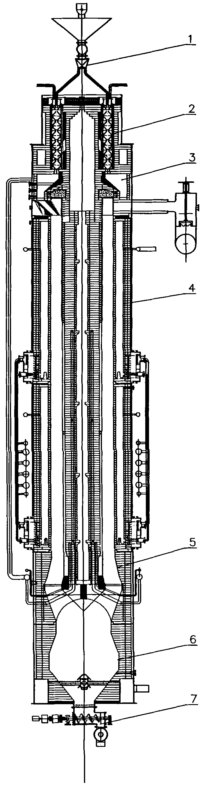
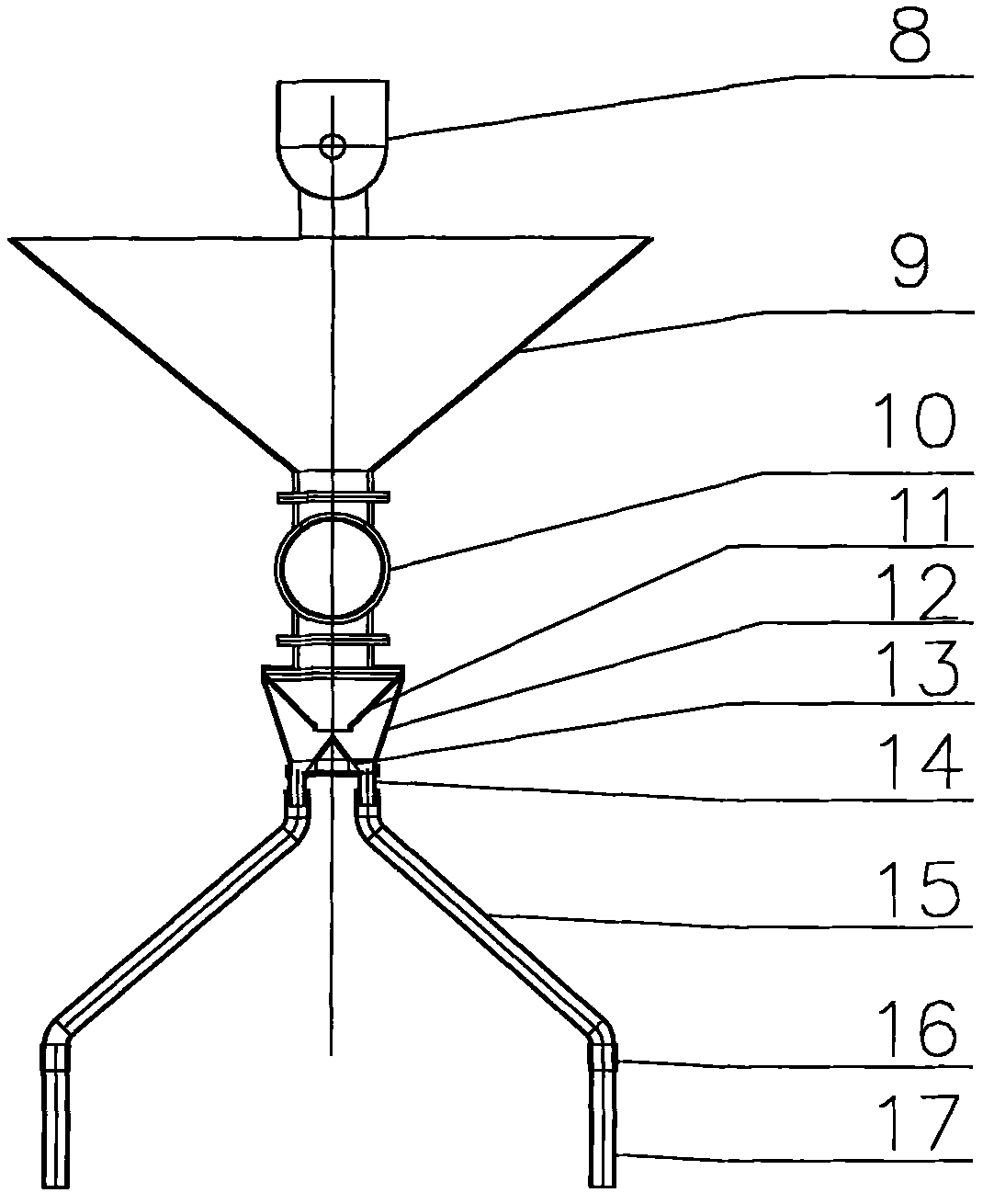
[0020]A coal pyrolysis furnace, comprising: a coal feeding device 1 for the coal pyrolysis furnace, a coal preheating device 2 for the coal pyrolysis furnace, a preheating coal feeding device 3 for the coal pyrolysis furnace, and a coal pyrolysis furnace coal The heating device 4 of the coal pyrolysis furnace, the coke reforming device 5 of the coal pyrolysis furnace, the CDQ device 6 of the coal pyrolysis furnace, and the coke pushing device 7 of the coal pyrolysis furnace; the coal feeding device 1 of the coal pyrolysis furnace includes a spiral Coal feeder 8, hopper 9, rotary coal feeder 10, funnel plate 11, coal distributor 12, equalizer 13, casing 14, feeding pipe 15, movable casing 16 and straight pipe 17; spiral coal feeder 8 is provided with a hopper 9, the hopper 9 is connected to the rotary coal feeder 10 through the flange, the rotary coal feeder 10 is connected to the coal distributor 12, and the coal distributor 12 is connected to ...


PUM


Abstract

The invention relates to a coal pyrolysis furnace which comprises a coal inlet device (1) of the coal pyrolysis furnace, a coal preheating device (2) of the coal pyrolysis furnace, a preheated coal feeding device (3) of the coal pyrolysis furnace, a coal heating device (4) of the coal pyrolysis furnace, a coke modification device (5) of the coal pyrolysis furnace, a coke dry quenching device (6) of the coal pyrolysis furnace and a coke push and discharge device (7) of the coal pyrolysis furnace. A thermal circulation continuous coking process can utilize waste heat to dry and preheat coal fed into the furnace, thereby lowering energy consumption and reducing the generation of smoke dust; the oil gas yield is increased, no circulating water is used, no fresh water is consumed, no waste water or waste residue is generated, and the up-to-standard discharge of tail gas can be achieved through a bag-type dust remover; and the coal is conditioned, thereby widening coal types and coal sources, improving the coke quality and increasing the oil gas field. By utilizing a thermal circulation continuous coke furnace, the raw coal cost is lowered by 200 Yuan; the benefit of chemical products, methane gas, hydrogen gas and combustion gas can be increased by 700 Yuan; the profit for the production of one ton of coke can be up to 900 Yuan; and the profit and tax of a coking scale with an annual production of million tons can be up to 90 million Yuan.

Description

technical field [0001] The invention belongs to a coking oven, in particular to a coal pyrolysis furnace. Background technique [0002] At present, there are many problems in the coke industry, such as severe overcapacity, low industrial concentration, unreasonable industrial layout, low level of comprehensive utilization of resources, and environmental pollution. Now coking coal resources are in short supply, coal prices are rising, and coking enterprises are suffering large losses; the traditional coking process has low resource utilization and intermittent coal charging, which cannot eliminate serious environmental pollution. The task of energy saving and emission reduction is arduous; the traditional product recycling process requires a lot of investment and little income, and it is difficult to adapt to the current situation of fierce market changes; the pressure of the international market is increasing; high volatile coal is directly burned for power generation, which...

Claims


Application Information

Patent Timeline
Patent Type & Authority Patents(China)
IPC IPC(8): C10B15/00C10B53/04C10B31/00C10B33/00C10B39/02C10B57/10C10B57/00C10B21/10C10B47/00
CPCY02P20/129
Inventor 王新民
Owner SHANXI XINLI ENERGY TECH
Why Eureka
Try Eureka