Sludge vaporizing furnace

A technology of sludge gasification and gasification furnace, applied in sludge treatment, pyrolysis treatment of sludge, water/sludge/sewage treatment, etc., to improve efficiency, high-efficiency sludge treatment, save dehydration equipment and gas cooling The effect of equipment

Inactive Publication Date: 2013-03-27
南京绿展能源有限公司
View PDF3 Cites 4 Cited by
  • Summary
  • Abstract
  • Description
  • Claims
  • Application Information

AI Technical Summary

Problems solved by technology

[0005] The purpose of the present invention is to provide a sludge gasification furnace, thereby effectively solving the problems of gas cooling and water treatment at the same time

Method used


Image

  • Sludge vaporizing furnace
  • Sludge vaporizing furnace
  • Sludge vaporizing furnace

Examples


Embodiment 1

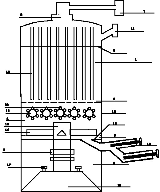
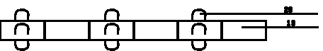
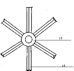
[0022] Such as figure 1 As shown, the gasification furnace is divided into upper and lower parts of the gasification chamber 1 and the motor chamber 2 by the furnace floor 19 with through holes. The gasification chamber 1 is divided into a drying area 3 and a gasification area from top to bottom. Zone 4, high temperature zone 5; the top of the drying zone 3 is provided with an air extraction hole 6, which is connected to the external air extraction system 7; the upper part of the drying area 3 is fixed with a sludge baffle plate 8, and the sludge The baffle plate 8 is provided with a plurality of pipe holes 9 such as Figure 4 As shown, the ventilation pipe 10 in the furnace passes through the pipe hole 9 on the sludge baffle 8 and runs through the entire drying area 3, and is supported by the sludge baffle 8. The diameter of the pipe hole 9 is slightly larger than that of the ventilation pipe 10 in the furnace. outer diameter; also includes a feed port 11, the feed port 11 i...


PUM


Abstract

The invention belongs to a device for converting an exhaust gas and sludge into a renewable combustion gas, and aims to provide a sludge vaporizing furnace for simultaneously solving combustion gas cooling and sludge water treatment. The vaporizing furnace is divided into an upper part which is a vaporizing room and a lower part which is a motor room through a drop bottom having a through hole, and the vaporizing room is divided into a drying zone, a vaporizing zone and a high temperature zone from top to bottom; the top of the drying zone is provided with an air exhaust hole, and is connected with an outside air exhaust system; and the upper portion of the drying zone is fixedly provided with a sludge baffle plate provided with a plurality of pores, furnace air ducts traverse the pores on the sludge baffle plate to link up the whole drying zone and are supported by the sludge baffle plate, and apertures of the pores are slightly greater than the external diameters of the furnace air ducts, so domestic sludge is reasonably and efficiently converted into the renewable combustion gas, dehydration and combustion gas cooling devices are saved, and the sludge treatment efficiency is improved. The sludge vaporizing furnace really realizes the sludge treatment having the advantages of energy saving, environmental protection and high efficiency.

Description

technical field [0001] The invention belongs to a gas generating device, in particular to a device for converting waste gas sludge into renewable gas, in particular to a sludge gasifier. [0002] Background technique [0003] A large amount of domestic sludge is produced in cities every day. Since most of the sludge is bound water rather than free water, it is not easy to treat. If the sludge is first dehydrated, when the moisture content is lower than 20%, most of the organic matter has been evaporated and cannot be recycled. At the same time, the moisture pretreatment of the sludge requires special equipment and investment , increasing the cost of sludge treatment. Not only that, because the pyrolysis of sludge is carried out at high temperature, the temperature of the regeneration gas obtained is very high. If the cooling work is not done well, it is likely to cause safety problems. [0004] Contents of the invention [0005] The object of the present invention is t...

Claims


Application Information

Patent Timeline
IPC IPC(8): C10J3/20C10J3/72C02F11/00C02F11/10C02F11/12
CPCY02P20/10
Inventor 雷泽兴雷建明雷建光
Owner 南京绿展能源有限公司
Why Eureka
Try Eureka