
Supercharged diesel engine system based on EGR (exhaust gas recirculation) high pressure chamber

A high-pressure cavity and diesel engine technology, applied in the direction of charging system, mechanical equipment, engine components, etc., can solve the problems of lower pressure than the intake pressure, intake pressure back into the exhaust pipe, increase fuel consumption, etc., to reduce NOx The effect of emissions

Inactive Publication Date: 2013-03-27
HARBIN ENG UNIV
View PDF6 Cites 7 Cited by
  • Summary
  • Abstract
  • Description
  • Claims
  • Application Information

AI Technical Summary

Problems solved by technology

[0003] When the supercharged diesel engine works in the medium-to-high load area, the outlet pressure of the compressor is basically greater than the exhaust pressure in front of the turbine. The pressure is lower than the intake pressure, which makes it difficult for the exhaust gas to flow back into the intake pipe, and even causes the intake pressure to flow back into the exhaust pipe, causing the diesel engine to have adverse phenomena such as reduced output power, increased fuel consumption, and unstable operation.
[0004] At present, some diesel engine EGR systems eliminate the influence of intake and exhaust pressure differences by installing structures such as throttle valves and Venturi tubes, but in actual use, not only will the efficiency of the compressor be reduced, and the normal use of the supercharger will be affected. It will reduce the intake pressure of the diesel engine, affect the power output, and increase fuel consumption

Method used


Image

  • Supercharged diesel engine system based on EGR (exhaust gas recirculation) high pressure chamber

Examples


Embodiment Construction

[0012] The present invention is described in more detail below in conjunction with accompanying drawing example:

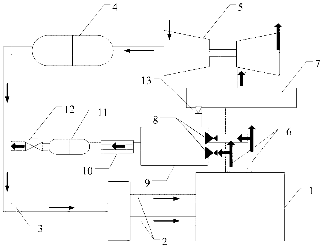
[0013] combine figure 1 , the technical scheme of the present invention is realized like this, and the present invention comprises: diesel engine 1, intake manifold 3, intake manifold 2, exhaust manifold 7, exhaust manifold 6, turbocharger 5, air intake intercooler 4, exhaust gas intercooler 11, EGR valve 12, EGR high-pressure chamber 9, one-way stop valve 8 and discharge valve 13 and other structures. A one-way stop valve 8 is installed at the inlet end of the EGR high-pressure chamber 9 connected to the exhaust manifold 6. One end of the outlet of the EGR high-pressure chamber 9 is connected with the exhaust gas filter 10, and the other end is connected with the exhaust main pipe 7. A discharge valve 13 is installed at the outlet end where the main pipe 7 is connected.

[0014] When the diesel engine normally works stably in each load area, since the intake pr...


PUM


Abstract

The invention aims to provide a supercharged diesel engine system based on an EGR (exhaust gas recirculation) high pressure chamber. The supercharged diesel engine system comprises a diesel engine and a turbosupercharger, wherein a turbine of the turbosupercharger is connected with an exhaust manifold of each steam cylinder of the diesel engine, and a compressor of the turbosupercharger is connected with an air inlet manifold of each steam cylinder through an air inlet main pipe; and the supercharged diesel engine system also comprises the EGR high pressure chamber and an EGR valve, wherein the EGR high pressure chamber is communicated with each exhaust manifold through a one-way stop valve, the EGR high pressure chamber is communicated with an exhaust main pipe through a discharge valve and is communicated with an air inlet main pipe through the EGR valve. The supercharged diesel engine system provided by the invention effectively utilizes the exhaust pulse energy, high pressure waste gas opens up a one-way isolating valve, waste gas is injected into the high pressure chamber, so the waste gas pressure in an EGR chamber is improved, and meanwhile, the discharge valve of the high pressure chamber guarantees a constant pressure in a cavity body, and finally the waste gas can smoothly return to the air inlet main pipe, and the NOx discharge of the diesel engine is lowered.

Description

technical field [0001] The invention relates to a diesel engine, specifically a diesel engine with a turbocharger. Background technique [0002] Theoretical research on EGR technology began in the 1960s and was first applied to gasoline engines. Since the 1970s, some foreign automakers have turned their research targets to diesel engines. Up to now, the power industry of various countries has increasingly used EGR technology to reduce nitrogen oxide emissions to meet the limit value stipulated by regulations. Its basic principle is to use the exhaust gas to circulate into the cylinder, on the one hand to dilute the oxygen concentration in the cylinder and inhibit the N2 oxidation reaction; on the other hand, to use the high specific heat capacity of the inert gas in the exhaust gas to reduce the combustion rate to achieve the purpose of reducing NOx emissions. [0003] When the supercharged diesel engine works in the medium-to-high load area, the outlet pressure of the comp...

Claims


Application Information

Patent Timeline
IPC IPC(8): F02M25/07F01N3/021F01N3/02F02B29/04F02M26/05F02M26/13F02M26/23F02M26/35
CPCY02T10/146Y02T10/121Y02T10/12
Inventor 王银燕杜骏杨传雷王贺春冯永明高占斌孙永瑞
Owner HARBIN ENG UNIV
Learn More