Stator and rotor assembly for high-power high-speed high-efficiency turbodrills
A turbo drilling tool, high-power technology, applied in the field of oil drilling, to achieve the effect of increasing the speed of the drilling tool, improving efficiency, and avoiding longitudinal movement
- Summary
- Abstract
- Description
- Claims
- Application Information
AI Technical Summary
Problems solved by technology
Method used
Image

Examples
specific Embodiment approach 1
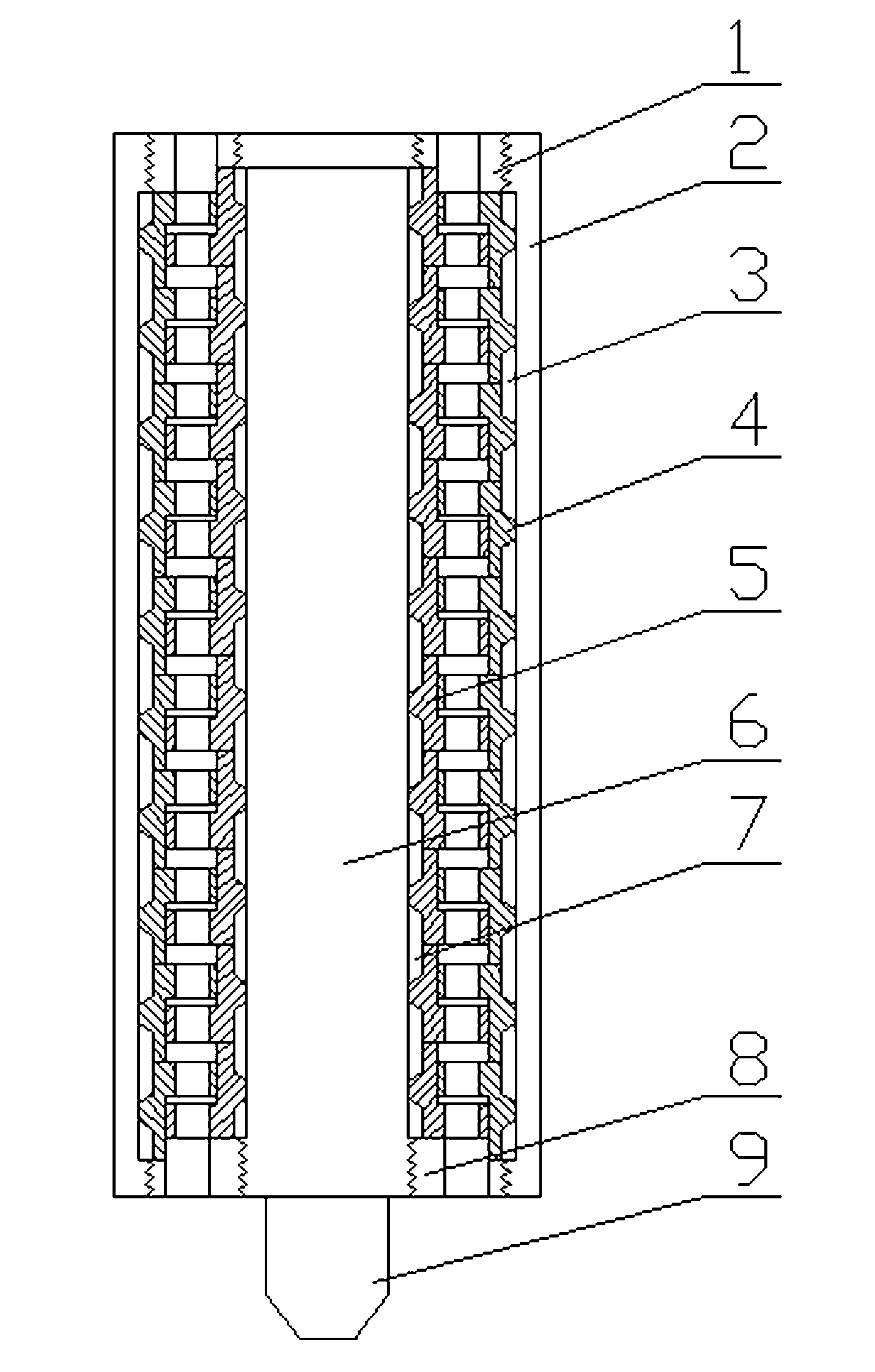
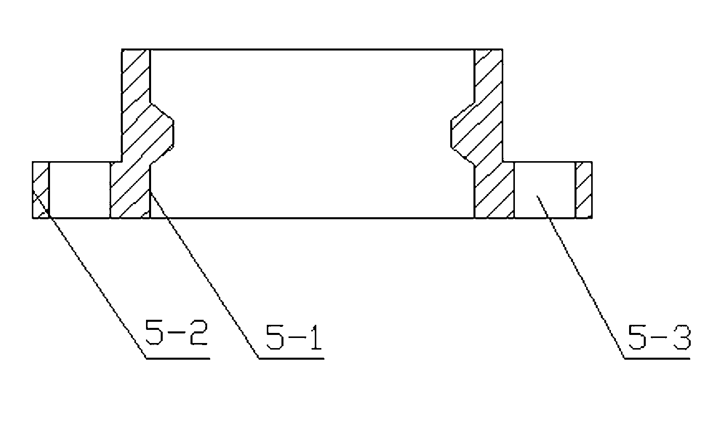
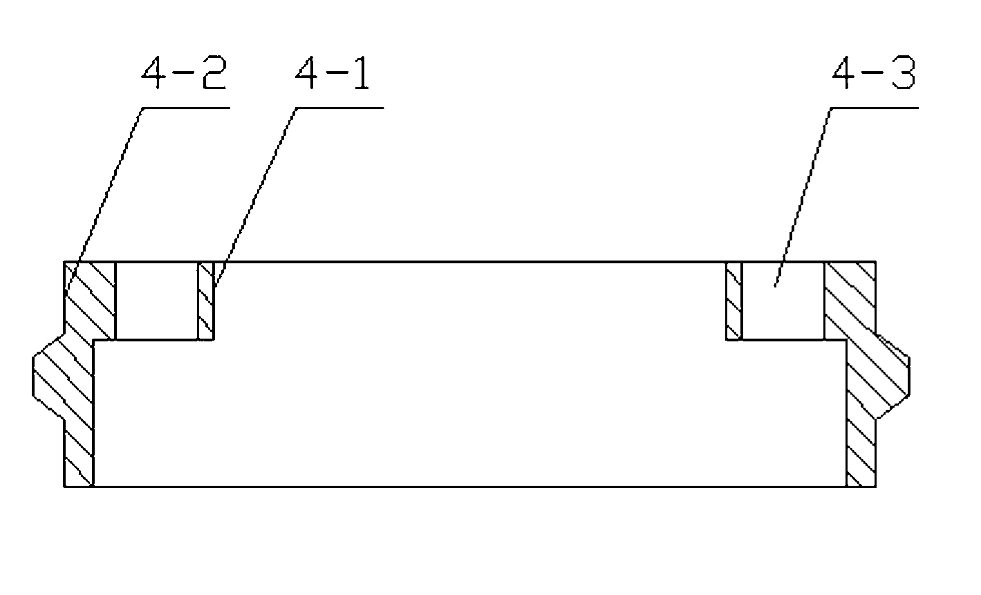
[0025] Specific embodiment 1: This embodiment is described in conjunction with each figure. The high-power, high-speed, high-efficiency turbodrill stator and rotor assembly of this embodiment includes a shaft 6, a housing 2, a stator 4 and a rotor 5, and stator blades are arranged on the stator 4 The rotor 5 is equipped with a rotor blade disk, the stator blade disk and the rotor blade disk form a stage, the degree of reaction of the stage is less than 0.5, the inner wall of the stage is set on the shaft 6, and there are ten stages on the shaft 6. The end faces between them are press fit, the lower end of the shaft 6 is provided with a drill bit 9, and the outer wall of the stage is covered with a shell 2. The stator blade disc comprises a cylindrical stator inner disk 4-1, a cylindrical stator outer disk 4-2 and a spline-shaped stator blade 4-3, and the stator blade 4-3 is uniform The rings are distributed on the stator blade disk centered on the axis, and are located between...
specific Embodiment approach 2
[0027] Specific embodiment two: This embodiment is described in conjunction with each figure. The stage pressure drop of this embodiment is 450-600kPa, the volume flow rate is 28-32L / s, and when the rotor speed is 2500-3300rpm, the stage efficiency is 60-75%. The power is 8-12kW. With such setting, according to the low-speed decompression characteristics of the stage, when the speed deviates from the design speed, the pressure drop of the stage will decrease, and the working state of the turbodrill can be judged according to the ground pressure, which is convenient for the drill staff to monitor and operate remotely. Other compositions and connections are the same as in the first embodiment.
specific Embodiment approach 3
[0028] Specific implementation mode 3: This implementation mode is illustrated in conjunction with various figures. In this implementation mode, the stage pressure drop is 535kPa, the volume flow rate is 30L / s, and when the rotor speed is 3000rpm, the stage efficiency can reach 70%, and the power is 11kW. With such setting, according to the low-speed decompression characteristics of the stage, when the speed deviates from the design speed, the pressure drop of the stage will decrease, and the working state of the turbodrill can be judged according to the ground pressure, which is convenient for the drill staff to monitor and operate remotely. Other compositions and connections are the same as those in Embodiment 1 or Embodiment 2.
[0029] The working principle of the high-power, high-speed and high-efficiency turbodrill is as follows: the drilling fluid from the high-pressure drilling pump on the ground passes through the drill pipe of the turbodrill, enters the stator 4 and r...
PUM
 Abstract
Description
Claims
Application Information
 - R&D
- Intellectual Property
- Life Sciences
- Materials
- Tech Scout
- Unparalleled Data Quality
- Higher Quality Content
- 60% Fewer Hallucinations
Browse by: Latest US Patents, China's latest patents, Technical Efficacy Thesaurus, Application Domain, Technology Topic, Popular Technical Reports.
© 2025 PatSnap. All rights reserved.Legal|Privacy policy|Modern Slavery Act Transparency Statement|Sitemap|About US| Contact US: help@patsnap.com