Automatic crucible dumping and cleaning system for electronic kilns

A technology for cleaning device and saggar, applied in descaling devices, furnaces, furnace components, etc., can solve problems such as unseen technical enlightenment, and achieve the effects of improving material pouring and cleaning efficiency, ensuring cleaning quality, and reducing work intensity

Inactive Publication Date: 2013-04-03
唐山盛梅陶瓷有限公司
View PDF3 Cites 16 Cited by
  • Summary
  • Abstract
  • Description
  • Claims
  • Application Information

AI Technical Summary

Problems solved by technology

Due to electronic powders such as color phosphor powder, lamp powder, barium titanate, strontium titanate, yttrium trioxide, titanium dioxide, zirconium dioxide, bismuth oxide, alumina, lead zirconate titanate, ferrite magnetic powder and lithium iron phosphate Etc. Due to the influence of factors such as static electricity, viscosity, and humidity in the working environment, when the burnt electronic powder material is poured out of the sagger, the phenomenon of sticking to the bowl will appear more or less (only the degree difference), the so-called The phenomenon of sticking to the bowl means that the burned electronic powder material remains in the sagger. If the accumulated or sticky clinker in the dry saggar is not removed, then the powder to be fired will be loaded again. Pollution will be generated when electronic po

Method used


Image

  • Automatic crucible dumping and cleaning system for electronic kilns
  • Automatic crucible dumping and cleaning system for electronic kilns
  • Automatic crucible dumping and cleaning system for electronic kilns

Examples


Embodiment Construction

[0020] In order to enable the examiners of the patent office, especially the public, to understand the technical essence and beneficial effects of the present invention more clearly, the applicant will describe in detail the following in the form of examples, but none of the descriptions to the examples is an explanation of the solutions of the present invention. Any equivalent transformation made according to the concept of the present invention which is merely formal but not substantive shall be regarded as the scope of the technical solution of the present invention.

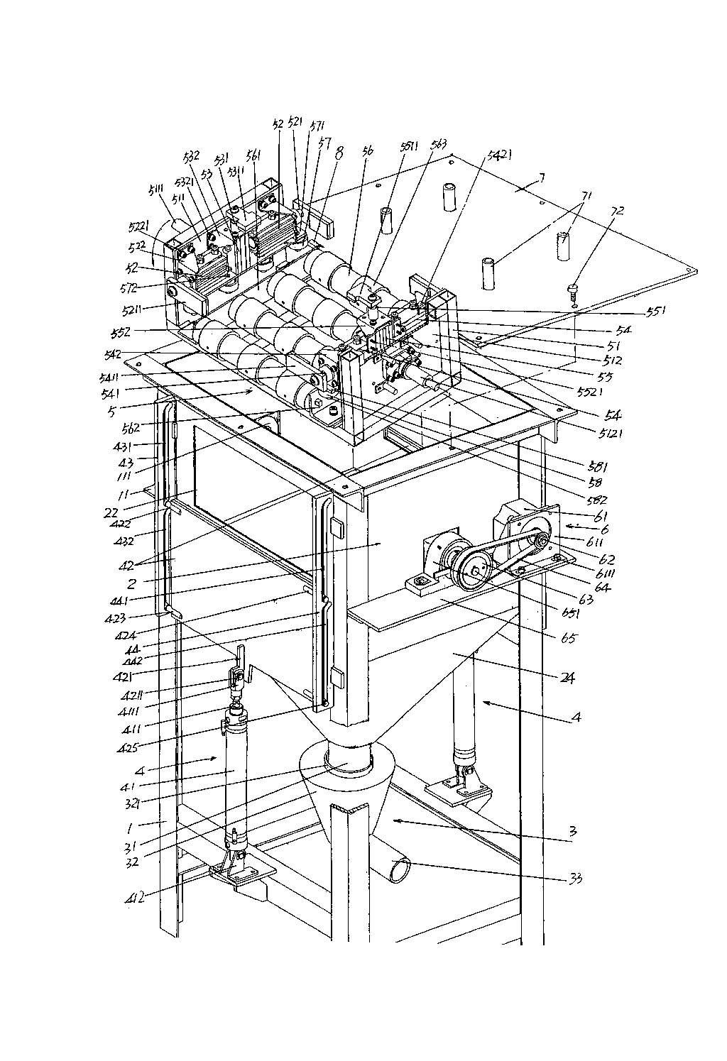
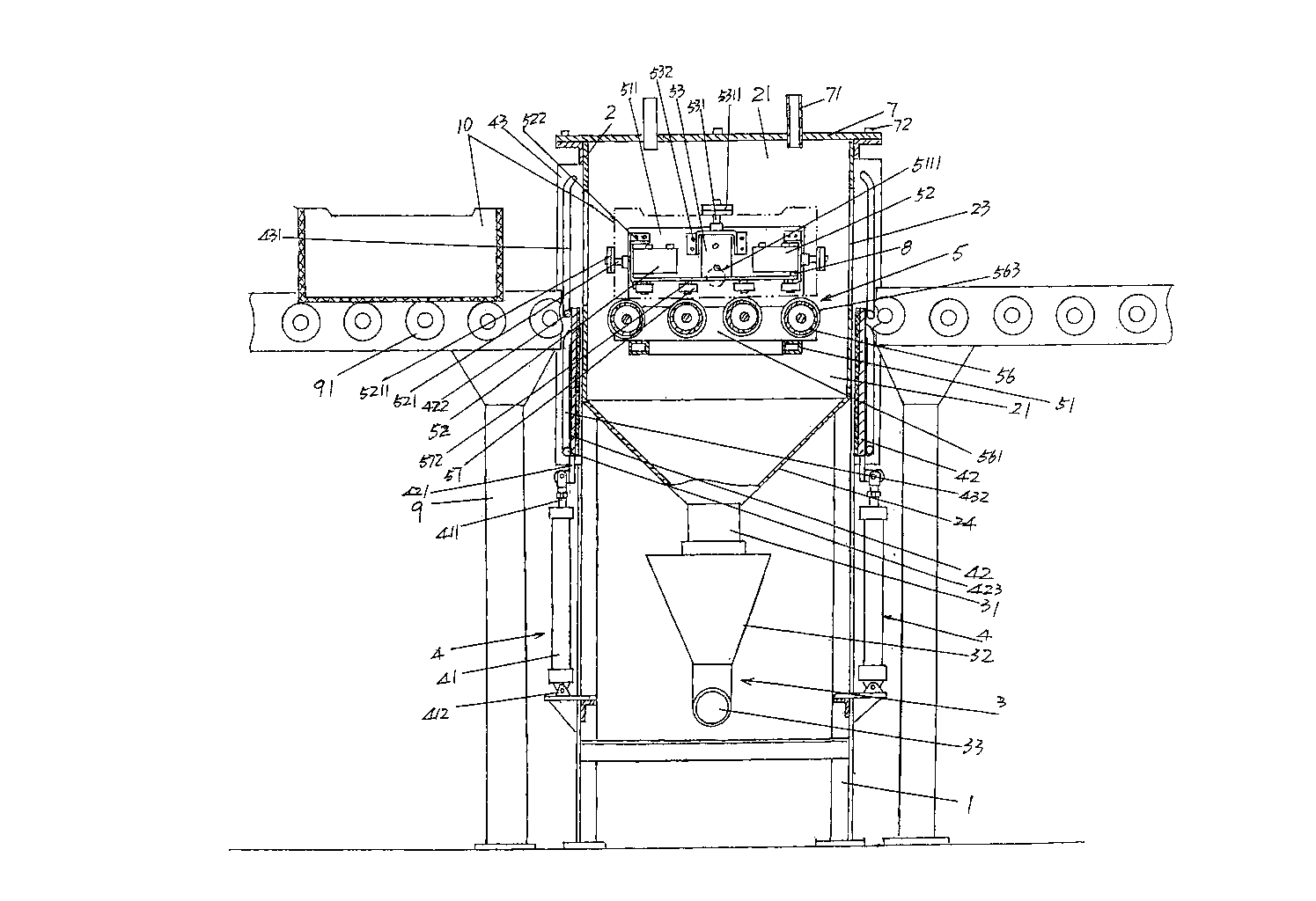
[0021] See figure 1 , a box frame 1 with a frame structure is given, and the box frame 1 is arranged on the sagger conveying frame 9 ( image 3 shown) on the channel. A receiving box 2 is fixed on the box frame 1, and one side of the upper part of the receiving box 2 is provided with a image 3 The illustrated saggar 10 loaded with material enters the sagger introduction port 22 in the receiving box cavity ...


PUM


Abstract

An automatic crucible dumping and cleaning system for electronic kilns belongs to the technical field of accessory facilities for electronic kilns. The automatic crucible dumping and cleaning system comprises a box underframe, a receiving box, a material discharge mechanism, a pair of door opening and closing mechanisms, a crucible-holding mechanism, a power transmission mechanism and a top cover; the receiving box is fixed on the box underframe, one side of the upper part of the receiving box is provided with a crucible inlet, and the other side of the upper part of the receiving box is provided with a crucible outlet; the material discharge mechanism is connected with the bottom of the receiving box; the door opening and closing mechanisms are arranged on the box underframe, one of the door opening and closing mechanisms corresponds to the crucible inlet, and the other door opening and closing mechanism corresponds to the crucible outlet; the crucible-holding mechanism is supported on the wall of the receiving box; the power transmission mechanism is fixed on the box underframe, and is connected with the crucible-holding mechanism; the top cover is fixed on the box underframe and corresponds to the open part of the top of the cavity of the receiving box, and a group of blowing tube connectors are arranged on the top cover, and are connected with an air source device. The automatic crucible dumping and cleaning system has the advantages that: the working intensity of workers can be decreased, and moreover, the dumping and cleaning efficiency can be increased; the cleaning quality can be guaranteed; and the environment of a working site cannot be polluted.

Description

technical field [0001] The invention belongs to the technical field of auxiliary facilities for electronic kilns, and in particular relates to an automatic dumping and cleaning device for saggers used in electronic kilns. Background technique [0002] As known to those skilled in the art, when electronic powder is fired (also called sintering) by an electronic kiln, it is necessary to put the electronic powder raw material into a sagger (also called a crucible), and the sagger together with the The electronic powder enters the electronic kiln for firing. After firing, the fired electronic powder is carried out of the kiln by the sagger and dumped and supplied to the next process such as grinding. The empty box is cleaned and filled with raw electronic powder again. The body is fired in a kiln. It can be seen that the sagger belongs to the turnover container for recycling. Due to electronic powders such as color phosphor powder, lamp powder, barium titanate, strontium titan...

Claims


Application Information

Patent Timeline
IPC IPC(8): F27D3/00F27D25/00
Inventor 李巍刘向蕾平雪良
Owner 唐山盛梅陶瓷有限公司
Why Eureka
Try Eureka