Photoacoustic-fluorescence flow cytometer

A flow cytometer and fluorescence technology, used in fluorescence/phosphorescence, instruments, scientific instruments, etc., can solve the problems of missed detection, inability to detect dark matter, inability to detect fluorescence, etc., to eliminate non-confocal signals and improve system detection. The effect of sensitivity

Active Publication Date: 2013-04-10
SOUTH CHINA NORMAL UNIVERSITY
View PDF3 Cites 10 Cited by
  • Summary
  • Abstract
  • Description
  • Claims
  • Application Information

AI Technical Summary

Problems solved by technology

However, due to the dependence on the fluorescence detection of exogenous fluorescent dyes, the method has certain limitations: (1) it cannot detect dark matter (non-fluorescent substances); (2) the flu...

Method used


Image

  • Photoacoustic-fluorescence flow cytometer
  • Photoacoustic-fluorescence flow cytometer
  • Photoacoustic-fluorescence flow cytometer

Examples


Embodiment 1

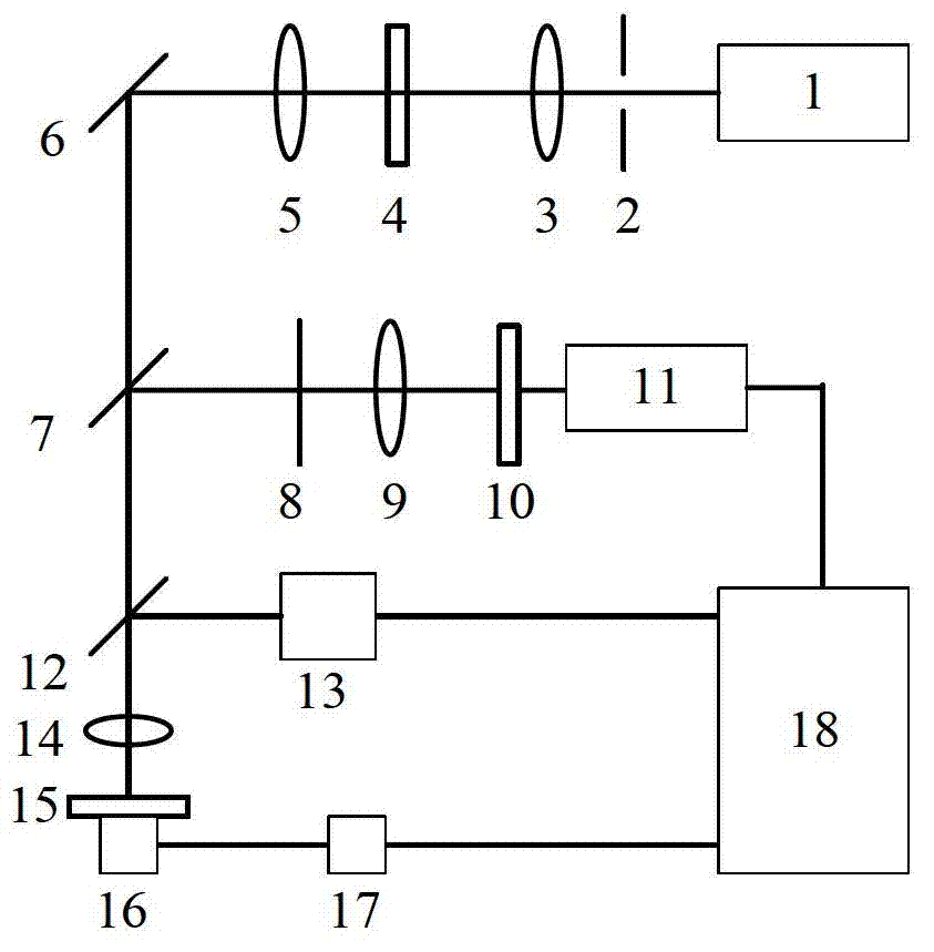
[0043] A photoacoustic-fluorescence flow cytometer, such as figure 1 As shown, it includes an optical excitation system, a fluorescent signal receiving system, a photoacoustic signal receiving system, a sample stage and a computer display control system; the optical excitation system is respectively connected with the fluorescence signal receiving system, the sample stage, and a computer display control system The system is respectively connected with the sample stage and the computer display control system, and the fluorescent signal receiving system is connected with the computer display control system; the computer display control system is electrically connected with the optical excitation system, the fluorescent signal receiving system, and the photoacoustic signal receiving system;

[0044] Described optical excitation system comprises excitation light source 1, diaphragm 2, cylindrical lens 3, slit A4, achromatic lens A5, reflecting mirror 6, dichroic beam splitter A12 a...

Embodiment 2

[0052] The method for detecting the number of cells using the photoacoustic-fluorescence flow cytometer of Example 1 comprises the following steps:

[0053] (1) Place the rhodamine sample in the center of the sample stage, place the microscopic objective lens directly above the sample stage, place the focused ultrasonic detector directly below the sample stage, and place the photomultiplier tube on the obliquely above the microscopic objective lens for the fluorescent light output At the mouth, the outside of the photomultiplier tube is closed with a black box;

[0054] (2) Start the photoacoustic-fluorescence flow cytometer, using a titanium sapphire pulsed laser as the excitation light source, the output laser wavelength is 532nm, the pulse width is 10ns, and the repetition frequency is 15Hz; the pulsed laser generated by the above laser is passed through the cylindrical lens After focusing to form a line spot, and then passing through the slit A, the achromatic lens A, refl...

Embodiment 3

[0062] The method for detecting the number of cells using the photoacoustic-fluorescence flow cytometer of Example 1 comprises the following steps:

[0063] (1) Place the ear blood vessels of the mouse in the center of the sample stage; place the microscope objective directly above the sample stage, place the focused ultrasound detector directly below the sample stage, and place the photomultiplier tube on the fluorescent light obliquely above the microscope objective. At the light outlet, the outside of the photomultiplier tube is closed with a black box;

[0064] (2) Start the photoacoustic-fluorescence flow cytometer, using a titanium sapphire pulsed laser as the excitation light source, the output laser wavelength is 532nm, the pulse width is 10ns, and the repetition frequency is 15Hz; the pulsed laser generated by the above laser is passed through the cylindrical lens After focusing to form a linear spot, and then passing through the slit A, the achromatic lens A, reflect...


PUM

PropertyMeasurementUnit
Excitation wavelengthaaaaaaaaaa
Pulse widthaaaaaaaaaa
Excitation wavelengthaaaaaaaaaa

Abstract

The invention discloses a photoacoustic-fluorescence flow cytometer. The flow cytometer comprises an optical excitation system, a fluorescence signal receiving system, a photoacoustic signal receiving system, a sample platform and a computer display controlling system, wherein the optical excitation system is connected with the fluorescence signal receiving system, the sample platform and the computer display controlling system; the photoacoustic signal receiving system is connected with the sample platform and the computer display controlling system; the fluorescence signal receiving system is connected with the computer display controlling system; the computer display controlling system is electrically connected with the optical excitation system, the fluorescence signal receiving system and the photoacoustic signal receiving system. According to the flow cytometer, as a pulse laser is adopted as a single excitation light source, a photoacoustic signal and a fluorescence signal of a substance to be detected are excited simultaneously, and simultaneously acquired through an upper passage and a lower passage, the photoacoustic signal and the fluorescence signal are detected in real time, and more information about a single cell and granules is acquired.

Description

technical field [0001] The invention belongs to the technical field of flow detection, and in particular relates to a photoacoustic-fluorescence flow cytometer and a detection method and application thereof. Background technique [0002] Flow cytometry is a technology developed in the 1970s. It integrates computer technology, laser technology, fluid mechanics, cytochemistry, and cellular immunology. It also has the functions of analyzing and sorting cells. This technology is a functional A detection method for quantitative analysis and sorting of single cells or particles at the horizontal level. [0003] At present, the most commonly used method of flow cytometry is fluorescence flow cytometry, which uses continuous laser light to irradiate cells or particles stained with fluorescent dyes in a high-speed flow state, and measures the intensity of their emitted fluorescence, so as to achieve the qualitative analysis of cells or particles. Or quantitative detection and analys...

Claims


Application Information

Patent Timeline
IPC IPC(8): G01N15/14G01N21/17G01N21/64
Inventor 杨思华李冰冰邢达
Owner SOUTH CHINA NORMAL UNIVERSITY
Why Eureka
Try Eureka