Portable ultrasonic imaging system receiving front-end device

An ultrasonic imaging system and receiving front-end technology, applied in radio wave measurement systems, instruments, etc., can solve the problems of increased static power consumption of bias circuits, increased insertion loss of echo signals, loss of echo signals, etc., to achieve portability The effects of simplification, system cost reduction, and signal-to-noise ratio improvement

Inactive Publication Date: 2013-04-10
INST OF ACOUSTICS CHINESE ACAD OF SCI
View PDF7 Cites 14 Cited by
  • Summary
  • Abstract
  • Description
  • Claims
  • Application Information

AI Technical Summary

Problems solved by technology

The introduction of high-voltage switches in the echo path will increase the insertion loss of the echo signal and increase the harmonic distortion
[0004] On the other hand, the prior art transceiver isolation diode bridge circuit such as figure 2 As shown, in order to ensure that it can work in the linear region of the diode, a larger

Method used


Image

  • Portable ultrasonic imaging system receiving front-end device
  • Portable ultrasonic imaging system receiving front-end device
  • Portable ultrasonic imaging system receiving front-end device

Examples


Embodiment

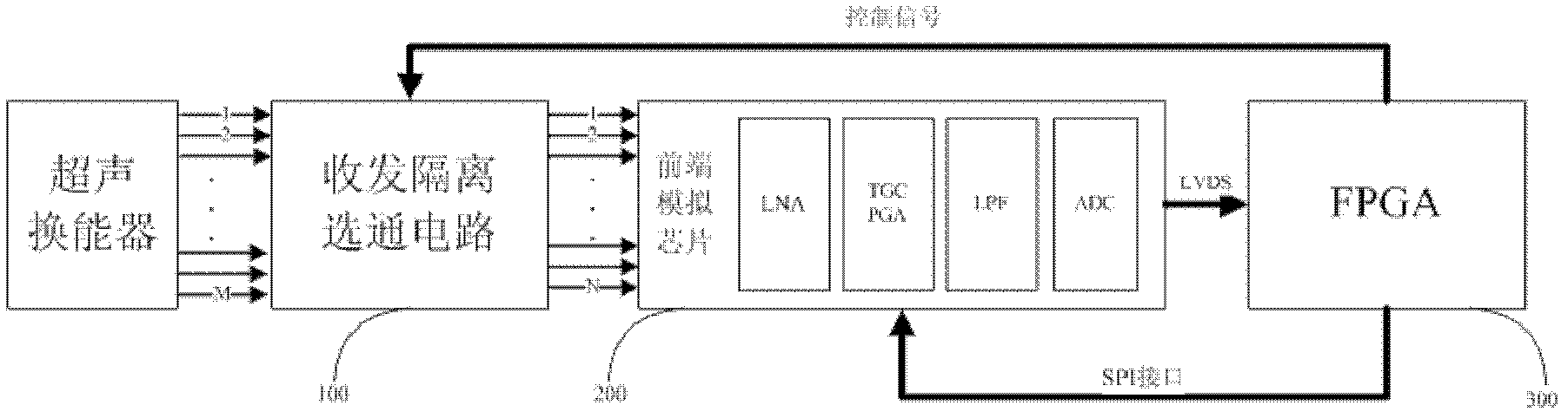
[0025] The block diagram of this embodiment is as image 3 As shown, it includes a transceiver isolation gating circuit 100 , a front-end analog chip 200 (this chip can use a type of chip with similar functions to the AFE5805, not limited to the AFE5805) and an FPGA main control unit 300 . The array elements of each ultrasonic transducer are directly connected to the diode bridge circuit module 100 for transceiver isolation to realize the functions of transceiver isolation and channel gating. The double-pole double-throw switch in the control is used to switch between different receiving channels. The echo signal passes through the front-end analog chip 200: first through the low-noise amplifier (LNA), then through the time-gain control (VCA), programmable gain (PGA) control, anti-aliasing low-pass filter (LPF) matching input signal, which is digitized by the analog-to-digital conversion circuit (ADC). The front-end analog chip 200 adopts an analog front-end chip AFE5805. T...


PUM


Abstract

The invention provides a portable ultrasonic imaging system receiving front-end device which is used for receiving and processing echo signals input by an ultrasonic transducer. The portable ultrasonic imaging system receiving front-end device is characterized by comprising sending and receiving isolated gate circuits which are connected in series sequentially, a front-end analog chip and a field programmable gata array (FPGA) main control unit. Optimized diode bridge circuits are adopted in the sending and receiving isolated gate circuits and the sending and receiving isolated gate circuits are controlled by the FPGA main control unit, each optimized sending and receiving isolated diode bridge circuit is connected with a transducer array element directly, wherein the optimized diode bridge circuits are provided with two inductances which are in a serial connection with the direct circuit bias access, and the specific circuit is characterized in that one ends, connected with the diode bridge, of a first bias resistance (R1) and a second bias resistance (R2) of the diode bridge circuit are respectively serially connected with a first inductance (L1) and a second inductance (L2), wherein the ranges of the first inductance and the second inductance are from several microhenries to hundreds of microhenries, and the portable ultrasonic imaging system receiving front-end device is powered by a single power supply.

Description

technical field [0001] The invention relates to the technical field of ultrasonic imaging, in particular to a receiving front-end device of a portable ultrasonic imaging system. Background technique [0002] The receiving front-end device of the ultrasonic imaging system in the prior art such as figure 1 As shown, the echo signals received by dozens or even hundreds of ultrasonic transducers need to be amplified and compensated for analog-to-digital conversion, and the collected multi-channel data should be sent to the back-end processor Data storage and post-processing. Each echo path in a traditional ultrasound imaging system needs to use multiple amplifier chips and a high-speed A / D chip with parallel output to amplify and sample the echo signal. Such an ultrasound imaging system that can meet medical needs requires a large number of amplifier chips and A / D chips to realize, and will form hundreds of digital interfaces, which will lead to many components used in the sys...

Claims


Application Information

Patent Timeline
IPC IPC(8): G01S7/526G01S7/529
Inventor 吕燚吴文焘汪东李平
Owner INST OF ACOUSTICS CHINESE ACAD OF SCI
Why Eureka
Try Eureka