Steel box component and steel box-concrete combined U-shaped girder composed of same

A technology for concrete and steel parts, applied in bridges, building components, bridge parts, etc., can solve the problems of large anti-corrosion and fire prevention area, prolonged construction period, high steel consumption, etc., achieve good friction and occlusion effect, reduce reinforcement area , the effect of shortening the construction period

Active Publication Date: 2013-04-17
ARCHITECTURAL DESIGN RES INST OF GUANGDONG PROVINCE
View PDF4 Cites 5 Cited by
  • Summary
  • Abstract
  • Description
  • Claims
  • Application Information

AI Technical Summary

Problems solved by technology

[0004] ⑴Compared with reinforced concrete beams, the existing steel-concrete beams use more steel, which is not only self-heavy, but also consumes more steel
[0005] (2) During the construction of the existing steel box-concrete beam, concrete needs to be poured into the closed rectangular steel box section, which is difficult to pour, and it is prone to the phenomenon that the concrete pouring is not dense and the vibration is not in place, which in turn affects the steel plate and concrete of the steel box The friction between them, the occlusal effect and the combination ability of the two, thus affecting the bearing capacity of the beam
[0006] (3) In the negative bending moment section of the existing steel-concrete beam, the section with the largest negative bending moment is usually the support at both ends of the beam, and the section steel located below has a problem of compression stability. ties, such as corner bracing or tie rods, etc., which makes the structure more complex and sometimes affects the requirements for building use
[0007] ⑷In the existing steel-concrete composite beam, the section steel is fixed on the lower surface of the concrete floor. Except the upper surface of the upper flange of the section steel is in contact with the concrete, the rest of the surfaces are exposed, so there are many exposed parts, and the anti-corrosion and fire prevention area It is also relatively large, resulting in higher processing costs and increased costs; steel box-concrete beams also have such problems
[0008] ⑸The construction process of the existing composite beam generally needs to build the construction formwork first, then pour concrete to form the composite beam, and then remove the construction formwork, which not only increases the construction cost, but also prolongs the construction period

Method used


Image

  • Steel box component and steel box-concrete combined U-shaped girder composed of same
  • Steel box component and steel box-concrete combined U-shaped girder composed of same
  • Steel box component and steel box-concrete combined U-shaped girder composed of same

Examples


Embodiment Construction

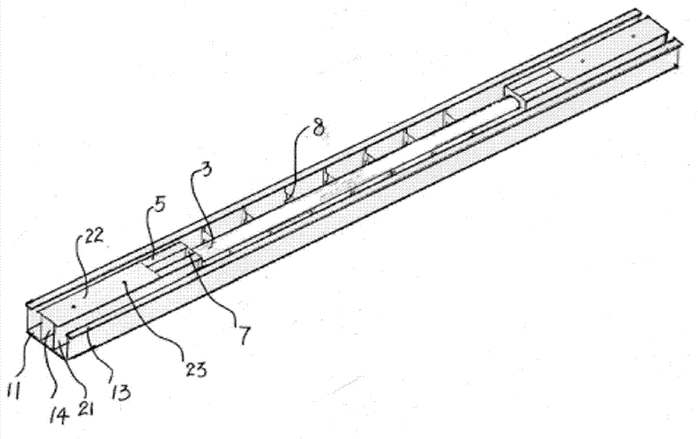
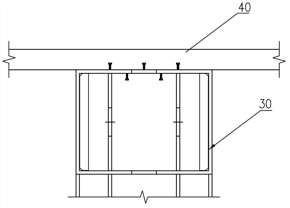
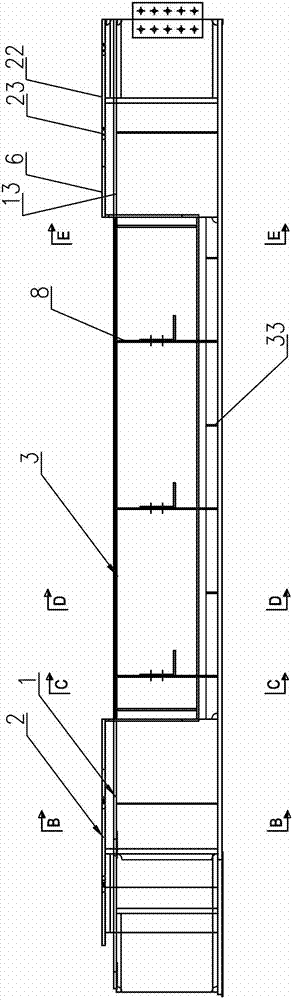
[0045] Such as Figure 2-13 As shown, it is a steel box assembly of the present invention, which is mainly composed of a U-shaped steel part 1, an n-shaped steel part 2 and a steel pipe 3 located at the mid-span position of the U-shaped steel part 1, and the length of the steel pipe accounts for half of the length of the U-shaped steel part The U-shaped steel part 1 is composed of an elongated base plate 11, a pair of outer plates 12 and an upper flange 13. The outer plates 12 are vertically arranged on both sides of the base plate 11, and the upper flange 13 is arranged on the top of the outer plate 12 of the U-shaped steel part. On the surface, the upper flange 13 is arranged horizontally along the longitudinal direction of the outer plate 12; the n-shaped steel part 2 is composed of a pair of vertically arranged elongated inner plates 21 and a top plate 22 arranged on the upper end of the inner plate 21, and the n-shaped steel part 2 is arranged on In the U-shaped space at ...


PUM


Abstract

The invention discloses a steel box component. The component is mainly composed of a U-shaped steel piece, n-shaped steel pieces and a steel tube which is arranged at a mid-span position of the U-shaped steel piece. The n-shaped steel pieces are arranged in U-shaped space at two ends of the U-shaped steel piece, the length directions of the n-shaped steel pieces are consistent with the longitudinal direction of the U-shaped steel piece, the lower ends of inner side plates of the n-shaped steel pieces are fixed on a bottom plate of the U-shaped steel piece and surround with the bottom plate of the U-shaped steel piece to form hollow pouring chambers with inner and outer ports, and pouring holes are opened on top plates of the n-shaped steel pieces. Vertical sealing plates are arranged at inner end openings of the pouring chambers, the steel tube is arranged in a suspension mode, steel openings at the two ends of the steel tube are connected onto the sealing plates respectively and blocked by the sealing plates; and gaps are arranged between the U-shaped steel piece and the n-shaped steel pieces and between the U-shaped steel piece and the steel tube. The invention further discloses a steel box-concrete combined U-shaped girder composed of the steel box component. By means of the steel box component and the steel box-concrete combined U-shaped girder composed of the same, the construction cost is saved, the construction period is shortened, the bearing capacity and the bending resistance at the girder support position are improved, and the reinforcement area and about 25% of dead-weight are reduced.

Description

technical field [0001] The present invention relates to a beam structure in the field of construction, in particular to a steel box assembly, and also to a steel box-concrete composite U-shaped beam composed of the steel box assembly, which can be used in bridges, industrial buildings, and civil building structures. Beams with large bearing capacity, large span, and limited cross-sectional area. Background technique [0002] Steel-reinforced concrete beams include steel-concrete beams, steel box-concrete beams, etc. Among them, steel-concrete beams refer to structures in which rolled or welded steel bars and steel bars are arranged in concrete, such as figure 1 As shown, the steel box-concrete beam 30 refers to: a beam with a square or rectangular cross-section welded by steel plates, pouring concrete and configuring steel bars in the closed space of the beam, when the steel box-concrete beam 30 is used as a floor beam, It is directly fixed on the lower surface of the floor...

Claims


Application Information

Patent Timeline
Patent Type & Authority Applications(China)
IPC IPC(8): E01D2/04E01D19/00E04C3/294
Inventor 陈星林景华张小良欧妍君孙学水王仕琪林扑强邱丽琴徐静陈航倪炜麟连丽凌赖鸿立关超王忠秋
Owner ARCHITECTURAL DESIGN RES INST OF GUANGDONG PROVINCE
Why Eureka
Try Eureka