
Functional electrical stimulation devices and systems and uses thereof

A technology of electrical stimulation and voltage source, applied in the field of electrical stimulation, can solve the problems of power loss and discomfort of therapy

Active Publication Date: 2015-12-16
UNIV HEALTH NETWORK
View PDF3 Cites 4 Cited by
  • Summary
  • Abstract
  • Description
  • Claims
  • Application Information

AI Technical Summary

Problems solved by technology

Another disadvantage of the predominantly used current source based devices is their signal slew rate, which is significantly less than that of voltage mode systems, thereby causing further power loss and making the therapy more uncomfortable

Method used


Image

  • Functional electrical stimulation devices and systems and uses thereof
  • Functional electrical stimulation devices and systems and uses thereof
  • Functional electrical stimulation devices and systems and uses thereof

Examples


example 1

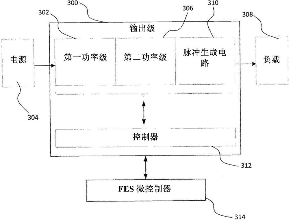
[0146] This example provides experimental results for an exemplary embodiment of the device. In this exemplary embodiment, the SMPSFES system is provided as a single channel stimulator comprising two power stages, a switched capacitor output circuit, and a digital block including a controller for a flyback converter and a circuits for buck and switched capacitor outputs. Flyback converters are generally configured to operate using current programmed mode (CPM). A flyback converter typically builds a high voltage output, which is fed into a buck converter, which in turn scales it down to the desired level. Finally, to construct the output current pulse, the switched capacitor circuit rapidly changes the voltage level and current direction. The buck duty cycle is controlled using hysteretic control. The converter and output blocks are designed and implemented on a printed circuit board (PCB), Figure 24 Its schematic diagram is shown in , and the digital part is implemented ...

example 2

[0171] This example provides the use of the following Figure 5 , 11 Experimental results obtained with prototypes constructed with 13 and 13 examples. That is, the four-channel stimulator is designed to include: a) a flyback power stage; b) four (4) stimulation channels, each including a buck converter, switched capacitor output circuit, and sensing circuit; and c) a digital block , the digital block includes controllers for the flyback power stage and pulse path. The first power stage establishes a high voltage output that feeds into each channel. A buck converter scales down the source voltage to the desired level. Finally, to construct the output current pulse, the switched capacitor circuit rapidly changes the voltage level and current direction. Use hysteretic control to control the buck converter duty cycle. Prototypes were fabricated using discrete components and a programmable DE-2, FPGA Altera evaluation board as digital blocks. Converters and output blocks are...

example 3

[0187] This example provides the results of an exemplary FES treatment method for improving brain and associated muscle function in individuals with neuromuscular deficits, merely for the various FES applications that can be facilitated by the FES devices and systems described above , methods, and treatments provide examples. In this example, the individual suffers from a post-stroke neurological disorder. It will be appreciated that such neurological disorders of the central nervous system may result from, for example, stroke, spinal cord injury, brain injury, multiple sclerosis, and any other traumatic and non-traumatic injury to the central nervous system.

[0188] individual description

[0189] The subject was a 22-year-old female who suffered a hemorrhagic stroke in the right anterior parietal region two years prior to participation in the study. The individual arrived at the personal rehabilitation center with a motor recovery status scored by CMSMR (Chedoke McMaster ...


PUM


Abstract

Disclosed herein is a functional electrical stimulation (FES) device and system. In one embodiment, sequential bipolar pulse stimulation may be provided to an area of a living body via one or more electrode leads applied to the area via a FES device comprising a current pulse generating circuit comprising output nodes for operative coupling to the one or more electrode leads, and configured for operative coupling to a voltage supply. The current pulse generating circuit generally comprises positive and negative stimulation paths drawing from the voltage supply to respectively apply positive and negative currents through the area via the one or more electrode leads. In one example, the stimulation paths comprise respective capacitive elements, a capacitance ratio of which dictating, at least in part, an amplitude ratio of the positive and negative currents, wherein periodic alternative activation of the stimulation paths provides the sequential bipolar pulse stimulation. In another example, each path comprises a respective charging element and a respective activation switch, wherein each respective charging element is charged by the voltage supply and discharged upon activation of the respective activation switch to generate positive and negative current pulses respectively, such that a pulse rise time of the positive and negative current pulses is predominantly dictated by a switching speed of each respective switch. Systems and uses for these devices, and FES in general, are also described.

Description

technical field [0001] The present disclosure relates to electrical stimulation, and in particular to functional electrical stimulation devices and systems. Background technique [0002] The general principle of functional electrical stimulation (FES) is derived from the physiological process of nerve and muscle excitation. These excitations are the result of action potentials (APs) occurring in vivo, at the neuronal level. AP is a messenger signal of the nervous system. They occur in nervous system tissues in response to stimuli that may be natural or man-made. In the case of FES, these stimuli are electrical charge pulses. Depending on the magnitude, duration and frequency of these stimuli, they can induce excitation in different tissues. FES therapy utilizes these excitatory pulses to treat patients with defects in different regions of the body. Due to the complexity of generating APs, artificial electrical stimulation pulses capable of generating these APs may requi...

Claims


Application Information

Patent Timeline
Patent Type & Authority Patents(China)
IPC IPC(8): A61N1/36A61N1/04H03K3/02
CPCA61N1/36003A61N1/36034A61N1/36067A61N1/36103A61N1/3615A61N1/36171H03K3/78A61N1/0476A61N1/36125A61N1/36167
Inventor 米洛斯·R·波波维奇马西莫·塔鲁利亚历山大·普罗迪奇彼得·莱恩
Owner UNIV HEALTH NETWORK
Learn More