
Ordered porous gold nanorod array and preparation method and application thereof

A nanorod array, gold nanorod technology, applied in the fields of nanostructure manufacturing, nanotechnology, nanotechnology, etc., can solve the problems of inability to obtain gold nanorod arrays, limited contribution, increased cost and complexity, etc., to improve SERS. Activity, consistency and repeatability, improve the effect of electromagnetic field enhancement

Inactive Publication Date: 2013-04-24
HEFEI INSTITUTES OF PHYSICAL SCIENCE - CHINESE ACAD OF SCI
View PDF4 Cites 17 Cited by
  • Summary
  • Abstract
  • Description
  • Claims
  • Application Information

AI Technical Summary

Problems solved by technology

However, there are deficiencies in both the gold nanorod array coated with silver on the top and its preparation method. First, the nanounits constituting the gold nanorod array—the gold nanorod has a solid structure with a smooth surface, and its SERS The activity only comes from the coupled electric field between the nanorods, which has a limited contribution to the enhancement of SERS activity; secondly, the silver nanoparticles coated on the top of the gold nanorods improve the SERS performance of the product, but also increase the cost and complexity of the preparation. ; Again, the specific surface area of ​​solid gold nanorods with a smooth surface is low, which is extremely unfavorable for the adsorption of target molecules in SERS detection; finally, the preparation method cannot make gold nanorod arrays with high SERS performance

Method used


Image

  • Ordered porous gold nanorod array and preparation method and application thereof
  • Ordered porous gold nanorod array and preparation method and application thereof
  • Ordered porous gold nanorod array and preparation method and application thereof

Examples


Embodiment 1

[0032] The concrete steps of preparation are:

[0033] Step 1, first place the aluminum oxide template coated with a gold film on one side in the mixed electrolyte, and electrodeposit it under a constant voltage direct current voltage of 0.2V for 10 minutes; wherein, the mixed electrolyte is electrolyzed by silver nitrate electrolyte and chloroauric acid The solution is mixed according to the ratio of gold ions and silver ions contained in the two at a ratio of 1:2 to obtain an alumina template with a gold film on one side and an array of gold-silver alloy nanorods deposited in the holes. Then put the aluminum oxide template with a gold film on one side and gold-silver alloy nanorod arrays deposited in the holes in a nitric acid solution with a concentration of 65wt% at 0°C for 10 minutes to obtain a gold film on one side and gold-silver alloy nanorod arrays in the holes. Alumina templates for porous gold nanorod arrays.

[0034] Step 2, first coating liquid methyl methacryla...

Embodiment 2

[0036] The concrete steps of preparation are:

[0037] Step 1, first place the aluminum oxide template coated with a gold film on one side in the mixed electrolyte, and electrodeposit it under a constant voltage direct current voltage of 0.35V for 7 minutes; wherein, the mixed electrolyte is electrolyzed by silver nitrate electrolyte and chloroauric acid The solution is mixed according to the ratio of gold ions and silver ions contained in the two at a ratio of 1:3 to obtain an alumina template with a gold film on one side and an array of gold-silver alloy nanorods deposited in the holes. Then put the aluminum oxide template with a gold film on one side and gold-silver alloy nanorod arrays deposited in the holes in a nitric acid solution with a concentration of 66wt% at 0.5°C for 7.5 minutes to obtain a gold film on one side and a gold-silver alloy nanorod array in the holes. Alumina template with porous gold nanorod arrays.

[0038] Step 2, first coating liquid methyl methac...

Embodiment 3

[0040] The concrete steps of preparation are:

[0041] Step 1, first place the aluminum oxide template coated with a gold film on one side in the mixed electrolyte, and electrodeposit it under a constant voltage direct current voltage of 0.5V for 5 minutes; wherein, the mixed electrolyte is electrolyzed by silver nitrate electrolyte and chloroauric acid The solution is mixed according to the ratio of gold ions and silver ions contained in the two at a ratio of 1:3.5 to obtain an alumina template with a gold film on one side and gold-silver alloy nanorod arrays deposited in the holes. Then put the aluminum oxide template with a gold film on one side and gold-silver alloy nanorod arrays deposited in the holes in a nitric acid solution with a concentration of 67wt% at 1°C for 5 minutes to obtain a gold film on one side and gold-silver alloy nanorod arrays in the holes. Alumina templates for porous gold nanorod arrays.

[0042] Step 2, first coating liquid methyl methacrylate on ...


PUM


Abstract

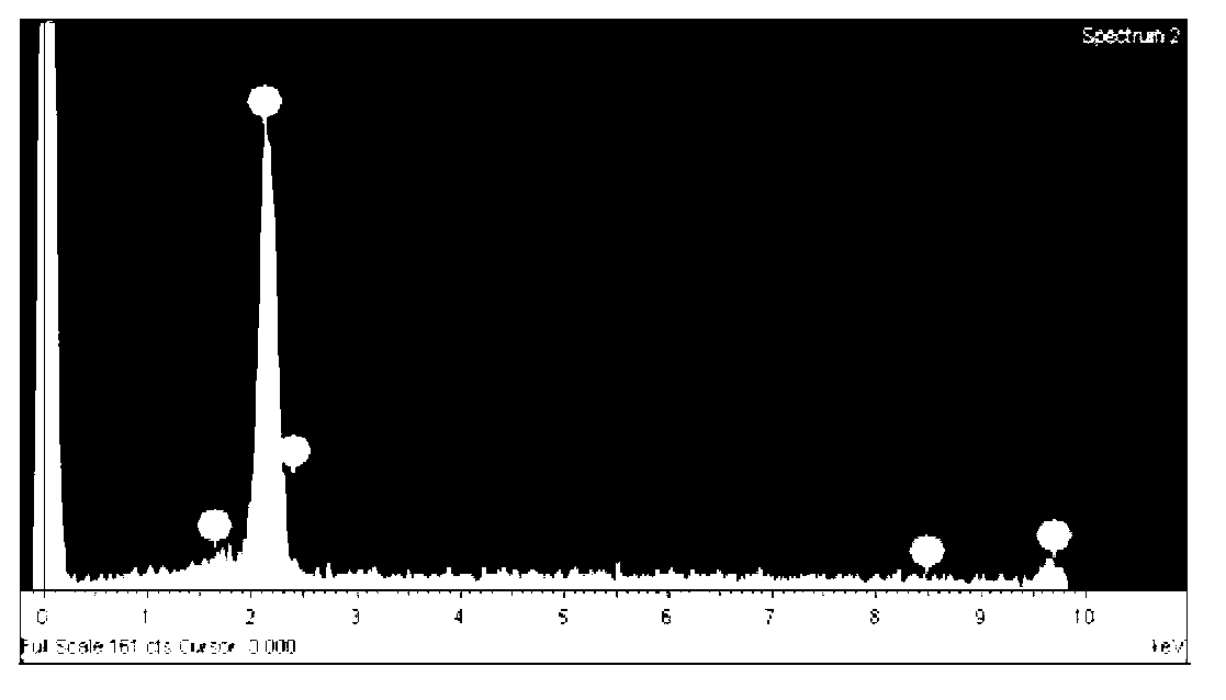
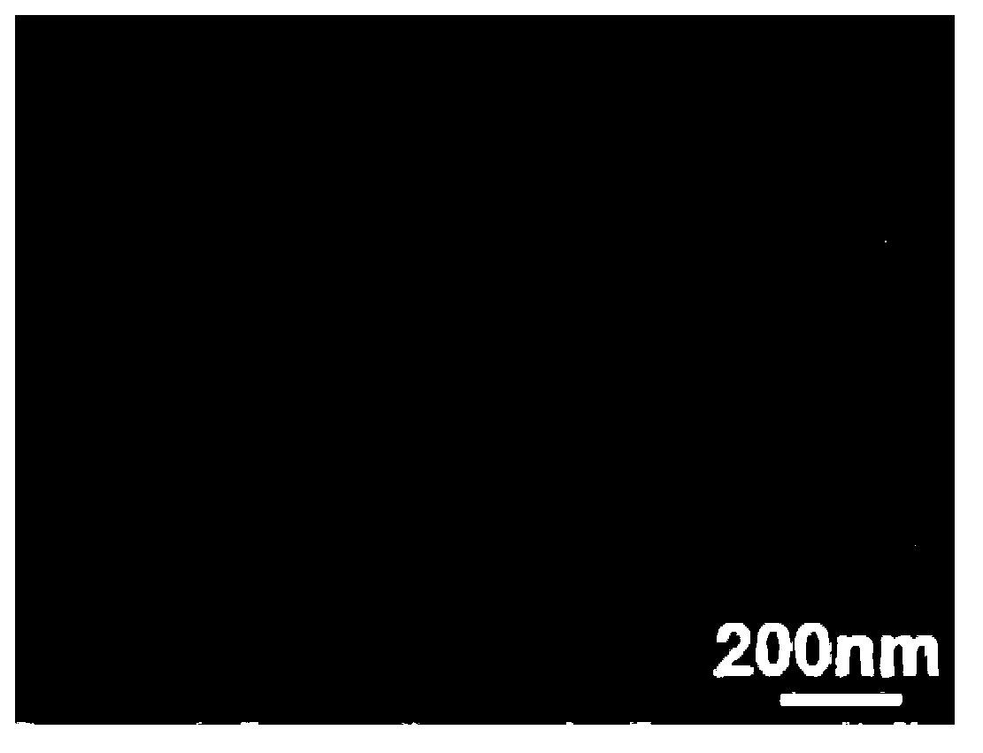
The invention discloses an ordered porous gold nanorod array and a preparation method and application thereof. The array is that the porous gold nanorod array is arranged on a methyl methacrylate substrate coated with a gold film. Length of porous gold nanorods on the gold film is 150-250nm, diameter of the nanorods is 50-70nm, and diameter of upper holes of the nanorods is 5-20nm. The method includes: an alumina template with one surface plated with a gold film is placed in mixed electrolyte to perform electrolytic deposition, the alumina template with the gold film plated on one surface and gold-silver alloy nanorods arrays deposited in holes is obtained, the alumina template is placed in a salpeter solution to react to obtain the alumina template with the gold film plated on one surface and porous gold nanorod arrays placed in the holes, liquid-state methyl methacrylate is coated on the other surface of the gold film of the alumina template with the gold film plated on one surface and porous gold nanorod arrays placed in the holes, the alumina template with the gold film plated on one surface and porous gold nanorod arrays placed in the holes is placed in an alkali solution to remove the alumina template after the liquid-state methyl methacrylate is solidified, and a target product is obtained. The ordered porous gold nanorod array can be used as a surface enhanced Raman scattering (SERS) active substrate to detect trace rhodamine.

Description

technical field [0001] The invention relates to a nanorod array, its preparation method and application, in particular to an ordered porous gold nanorod array, its preparation method and application. Background technique [0002] In recent years, the surface-enhanced Raman scattering (SERS) effect of nanostructures of noble metals such as gold, silver, and copper has attracted widespread attention. The SERS effect has become an important tool for biochemical and organic trace detection because of its "fingerprint" recognition ability, high sensitivity and easy rapid detection. Recently, people have made unremitting efforts to obtain nanostructured materials with SERS effect, as mentioned in a Chinese invention patent CN 102041507 B of the applicant whose authorization announcement date was April 25, 2012 A "Gold Nanorod Array Topped with Silver and Its Preparation Method and Application". The array described in this patent document is an array of gold nanorods coated with ...

Claims


Application Information

Patent Timeline
IPC IPC(8): B82B1/00B82B3/00C25D5/02C23C28/02G01N21/65
Inventor 陈斌孟国文黄竹林许巧玲朱储红唐海宾
Owner HEFEI INSTITUTES OF PHYSICAL SCIENCE - CHINESE ACAD OF SCI
Learn More