
Photocatalytic postposed internal-circulation anaerobic fluidized membrane bioreactor and working method thereof

A membrane bioreactor, anaerobic fluidization technology, applied in chemical instruments and methods, anaerobic digestion treatment, waste fuels, etc. To deal with problems such as high cost of raw materials and insignificant mineralization effect, to achieve the effect of realizing the treatment of organic pollutants that are easy to biochemically degrade and difficult to biochemically degrade, reducing reaction toxicity, and practical sewage and wastewater treatment and reuse processes

Inactive Publication Date: 2013-05-01
SHANDONG UNIV
View PDF6 Cites 13 Cited by
  • Summary
  • Abstract
  • Description
  • Claims
  • Application Information

AI Technical Summary

Problems solved by technology

This patent uses the principle of catalytic ozonation to treat the above-mentioned sewage and wastewater, and the raw material cost is high and has certain toxicity; solid catalyst and ultraviolet light synergistically catalyze ozonation to easily realize aromatic hydrocarbons, azos, etc. that are difficult to biochemically degrade Inorganization of organic matter, but the mineralization effect on organic matter that is easy to biodegrade, such as saturated chain hydrocarbons, is not obvious, and the simultaneous treatment of easily biodegradable and refractory organic pollutants in sewage and wastewater cannot be achieved

Method used


Image

  • Photocatalytic postposed internal-circulation anaerobic fluidized membrane bioreactor and working method thereof
  • Photocatalytic postposed internal-circulation anaerobic fluidized membrane bioreactor and working method thereof
  • Photocatalytic postposed internal-circulation anaerobic fluidized membrane bioreactor and working method thereof

Examples


Embodiment 1

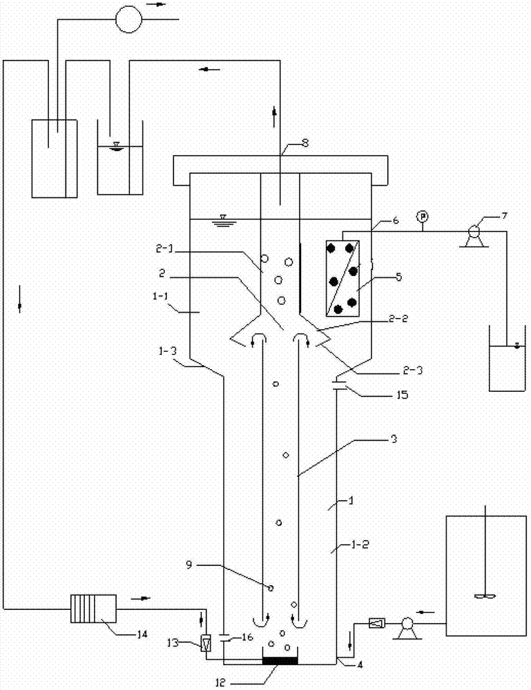
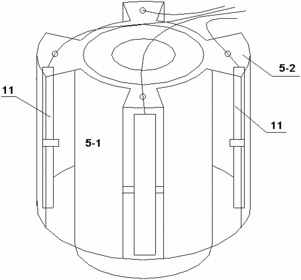
[0046] Such as Figure 1-2 shown.

[0047] A post-photocatalytic internal circulation anaerobic fluidized membrane bioreactor, including a reaction cylinder 1, a stripping cylinder 3, a three-phase separator 2 and a membrane module 5, and an inlet is installed at the bottom of the reaction cylinder 1 Water pipe 4 and air inlet pipe 14; biogas aeration disc 12, stripping cylinder 3 and three-phase separator 2 are arranged axially inside reaction cylinder 1 from bottom to top; The phase separator 2, the three-phase separator 2 includes a top-down guide tube 2-1 and an umbrella-shaped guide cover 2-2, and a direction is arranged on the outer edge of the umbrella-shaped guide cover 2-2. Inwardly folded guide edge 2-3, the upper end of the guide tube 2-1 communicates with the external gas outlet pipe 8 through the top cover of the reaction tube 1, and connects with the biogas aeration tray 12 through the air pump In the reaction cylinder 1, a membrane assembly 5 is arranged at a ...

Embodiment 2

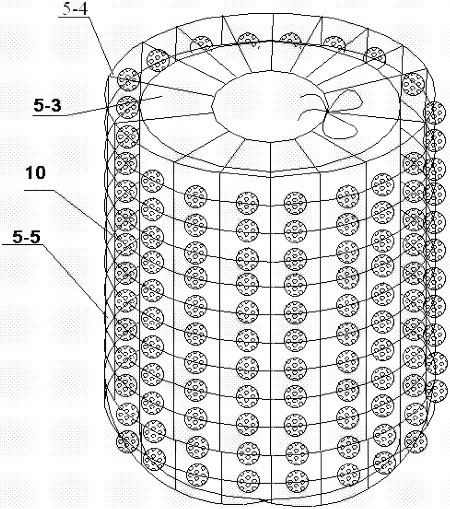
[0057] Such as figure 1 , 3 shown.

[0058] The internal circulation anaerobic fluidized membrane bioreactor with photocatalysis as described in Example 1, the difference is that the membrane module 5 is a hollow fiber ultrafiltration with a titanium dioxide light particle net 5-4 hanging on the outside. The film 5-3; the titanium dioxide light particle net 5-4 includes mesh wires 5-5 arranged in warp and weft, and titanium dioxide light particles 10 are hung on the mesh wires 5-5. The diameter range of the titanium dioxide light particles 5-4: 2-4mm.

[0059] The mesh wire 5-5 is sheathed on the outer surface of the hollow fiber ultrafiltration membrane 5-3 in the shape of a net bag. The rated pore diameter of the hollow fiber ultrafiltration membrane 5-3 is 0.01 micron. The total volume of the titanium dioxide light particles is 1 / 5 of the total volume of the hollow fiber ultrafiltration membrane.

[0060] Wherein, the preparation method of the titanium dioxide light pa...

Embodiment 3

[0069] A kind of working method that utilizes reactor treatment sewage as described in embodiment 1 or embodiment 2, comprises steps as follows:

[0070] (1) Add anaerobic activated sludge to the reaction cylinder 1 through the sludge filling port 15, and the volume of the added anaerobic sludge accounts for 1 / 6-1 / 5 of the volume of the entire reaction cylinder 1; Set hollow support 5-2, turn on the ultraviolet light source 11 on the hollow support;

[0071] (2) Open the water inlet 4, inject sewage into the reaction cylinder 1; open the biogas aeration disc 12, inject biogas into the reaction cylinder 1;

[0072] (3) The sewage rises to the three-phase separator 2 along the stripper 3: the biogas is discharged along the three-phase separator 2 and the outlet pipe 8; the sediment in the sewage settles along the space of the stripper 3 and is mixed with the active Anaerobic biological reaction occurs in sludge;

[0073] (4) The clear liquid in the sewage stays in the upper pa...


PUM

PropertyMeasurementUnit
diameteraaaaaaaaaa
particle diameteraaaaaaaaaa
water absorptionaaaaaaaaaa

Abstract

The invention relates to a photocatalytic postposed internal-circulation anaerobic fluidized membrane bioreactor. The photocatalytic postposed internal-circulation anaerobic fluidized membrane bioreactor comprises a reaction barrel, a gas stripping barrel, a three-phase separator and a membrane assembly, wherein a water inlet pipe and a gas inlet pipe are arranged at the bottom of the reaction barrel; and the membrane assembly is a cylindrical ceramic membrane loaded with nano-titanium dioxide particles, or the membrane assembly is a hollow fiber ultrafiltration membrane of which a light titanium dioxide particle mesh is hung on the outer surface. The invention further discloses a working method of the photocatalytic postposed internal-circulation anaerobic fluidized membrane bioreactor. An internal-circulation anaerobic treatment technology and a titanium dioxide photocatalytic technology are combined, and advantages of an anaerobic membrane bioreactor and a photocatalytic bioreactor are combined, so that quality of outlet water is obviously improved; and the membrane assembly is arranged at a supernatant part of a three-phase separation zone and doses not directly contact sludge, and nano-titanium dioxide has a photocatalytic effect, so that membrane pollution is greatly reduced, the service life of the membrane assembly is prolonged, and manpower and material resources required in a membrane replacing cycle are reduced.

Description

technical field [0001] The invention relates to an internal circulation anaerobic fluidized membrane bioreactor with post-photocatalysis and a working method thereof, belonging to the technical field of wastewater treatment and reuse. Background technique [0002] At present, biological methods are mostly used in sewage and wastewater treatment. Among them, anaerobic biological technology has broad application prospects because of its high production capacity. Anaerobic membrane bioreactor is a combination of anaerobic biological technology and membrane separation technology. Anaerobic flocculent sludge or granular sludge can effectively remove biodegradable organic pollutants in sewage and wastewater. Membrane separation can achieve efficient Solid-liquid separation, and further improve the water quality. However, the anaerobic membrane bioreactor has little effect on organic pollutants that are difficult to biodegrade and cannot be biodegraded (such as azo compounds, poly...

Claims


Application Information

Patent Timeline
Patent Type & Authority Applications(China)
IPC IPC(8): C02F9/14C02F3/28C02F1/32
CPCY02E50/30
Inventor 王燕韩绮马德方闫晗高宝玉岳钦艳李倩
Owner SHANDONG UNIV
Learn More