Supercharge Your Innovation With Domain-Expert AI Agents!

Self-excited push-pull type converter

A self-excited push-pull, converter technology, applied in the direction of transformer/inductor cooling, transformer/inductor coil/winding/connection, magnetic liquid, etc., can solve problems such as difficult guarantee, difficult processing, and damaged line sequence, etc. Achieve the effects of improved efficiency, small size, and simple winding

Active Publication Date: 2013-05-01
MORNSUN GUANGZHOU SCI & TECH
View PDF10 Cites 4 Cited by
  • Summary
  • Abstract
  • Description
  • Claims
  • Application Information

AI Technical Summary

Problems solved by technology

[0020] 1. It is difficult to wind the transformer of the saturated self-excited push-pull converter
[0021] see figure 1 , figure 2 , including the Royer circuit and the Jensen circuit. The transformer B1 in the circuit uses the magnetic core saturation characteristic for push-pull oscillation. In order to achieve magnetic saturation, the transformer B1 is wound with a magnetic core without an air gap, and the magnetic winding system is generally used. 2011 In 2019, nearly 70 million self-excited push-pull converter micropower power supply modules were newly added in the global industrial field, all of which adopt closed magnetic circuit magnetic surround transformers, and most of them have a diameter of less than 10mm. Image 6 The schematic diagram shows the structure of this magnetic ring. Since the magnetic circuit is closed, the enameled wire must pass through the hole in the middle of the magnetic ring during winding, which is difficult to wind.
figure 1 and figure 2 The medium transformer B1 must use magnetic saturation to realize the push-and-change conversion, and the air gap cannot be opened, which brings great difficulties to the winding. At present, so many turns of enameled wire are wound on a small magnetic ring with a diameter of less than 10mm. No matter whether it is a machine Winding or manual winding, there are processing difficulties
Machine winding is used. When the first layer is wound and the second layer is wound, the enameled wire of the second layer is difficult to be stacked on the first layer, which will destroy the wire sequence of the first layer. The result is that the winding is worse and more chaotic; In manual winding, the number of turns depends entirely on the operator's memory. It is difficult to ensure that one or two turns are not made, or one or two turns are less. Once the number of turns is changed, the output voltage will deviate. After the transformer is installed, the original function cannot be realized
[0022] Due to the large amount of hand winding involved, this is also the reason why the manufacturing cost of micropower power modules using self-excited push-pull conversion circuits remains high
[0023] 2. The volume of the unsaturated self-excited push-pull converter transformer is relatively large
[0024] This is described on pages 57 to 70 of the "Power Conversion Technology" mentioned above. It can also be seen from the nearly 70 million micro-power power modules of self-excited push-pull converters added every year in the global industrial field. , the unsaturated self-excited push-pull converter transformer has not been applied due to its volume and the following reasons
[0025] 3. The unsaturated self-excited push-pull converter has poor reliability
[0028] 1) It is difficult to wind the transformer of the saturated self-excited push-pull converter;
[0029] 2) The volume of the unsaturated self-excited push-pull converter transformer is relatively large;
[0030] 3) The unsaturated self-excited push-pull converter has poor reliability

Method used


Image

  • Self-excited push-pull type converter
  • Self-excited push-pull type converter
  • Self-excited push-pull type converter

Examples


Embodiment 1

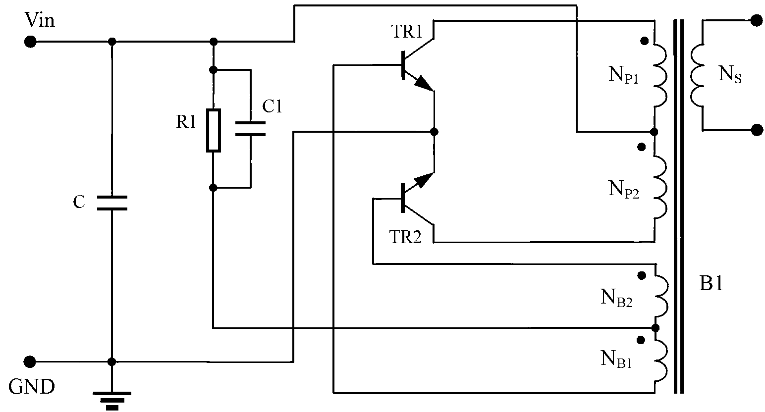
[0065] The schematic diagram of the self-excited push-pull converter of the first embodiment adopts figure 1 circuit, Figure 7 It is a schematic diagram of the combined magnetic core used in the transformer B1 of the first embodiment. The relatively common ER7.5 magnetic core is used. The magnetic material comes from TPW33 of Tiantong Holdings Co., Ltd. The appearance is as follows Figure 7 As shown, the six faces indicated by 22 are mirror faces.

[0066] Such as figure 1 As shown, the first embodiment is made into a 5V to 5V converter circuit with an output current of 250mA, the capacitor C is 2.2uF, the capacitor C1 is 0.33uF, the resistor R1 is 1.8KΩ, the transistors TR1 and TR2 are S8050 transistors, and the transformer B1 is all used Trace formation on the circuit board, winding N P1 and N P2 4 turns respectively, the feedback winding N B1 and N B2 were 1 turn, while the output winding N S It is 10 turns with a center tap, and connected to the full-wave rectific...

Embodiment 2

[0078] The schematic diagram of the self-excited push-pull converter of the second embodiment adopts figure 1 circuit, Figure 7 It is a schematic diagram of the combined magnetic core used in the transformer B1 of the second embodiment. The more common ER7.5 magnetic core is used, and the magnetic material is still the above-mentioned TPW33. The appearance is as follows Figure 7 As shown, the six faces indicated by 22 are mirror faces.

[0079] Such as figure 1 As shown, the second embodiment is made into a 5V to 5V converter circuit with an output current of 250mA. The capacitor C is 1uF, the capacitor C1 is 0.22uF, the resistor R1 is 1.5KΩ, the triodes TR1 and TR2 are S8050 triodes, and the transformer B1 is all circuit Board trace formation, winding N P1 and N P2 4 turns respectively, the feedback winding N B1 and N B2 were 1 turn, while the output winding N S It is 10 turns with a center tap, and connected to the full-wave rectification circuit on the circuit boar...

Embodiment 3

[0088] figure 1 is the schematic diagram of the self-excited push-pull converter of the third embodiment, Figure 7 The combined magnetic core used in the transformer B1 of the third embodiment is different from the second embodiment in its number of winding turns and installation method. Such as figure 1 As shown, the third embodiment is made into a 5V to 5V converter circuit with an output current of 250mA, the capacitor C is 1uF, the capacitor C1 is 0.22uF, the resistor R1 is 1.5KΩ, the transistors TR1 and TR2 are FMMT491 transistors, and the transformer B1 is in ER7. 5 The magnetic core is wound on the matching skeleton, and is wound with high-strength enameled wire with a temperature resistance of 180°C. The winding N P1 and N P2 8 turns respectively, the feedback winding N B1 and NB2 were 2 turns, while the output winding N S It is 18 turns with a center tap, and connected to a full-wave rectification circuit. The diode in the full-wave rectification circuit is RB16...


PUM

PropertyMeasurementUnit
saturation flux densityaaaaaaaaaa

Abstract

The invention discloses a self-excited push-pull type converter. More than two magnetic cores are combined into a whole to realize magnetic saturation which is same with that of an integral magnetic core so as to realize the conversion of a push-pull triode. The self-excited push-pull type converter is realized by the method that mirror surfaces are used as the contact surfaces of the magnetic cores, and a magnetic solution is added at the connecting part of the mirror surfaces or the magnetic cores are baked at a high temperature to realize the magnetic saturation. The self-excited push-pull type converter has high conversion efficiency, excellent consistency and high reliability. Meanwhile, an obtained transformer has the characteristics of small size and simple winding technology.

Description

technical field [0001] The invention relates to a switching power supply, in particular to a self-excited push-pull converter type switching power supply. Background technique [0002] The existing self-excited push-pull converter, the circuit structure comes from the self-excited oscillating push-pull transistor single-transformer DC converter invented by G.H.Royer in 1955, also known as the Royer circuit, which is also a high-frequency conversion control circuit. Part of the circuit comes from the self-excited push-pull double transformer circuit invented by Jen Sen in the United States in 1957, which was later called the self-oscillating Jensen circuit or Jensen circuit; these two circuits , later generations are collectively referred to as self-excited push-pull converters. The relevant working principle of the self-excited push-pull converter is described on pages 67 to 70 of "The Principle and Design of Switching Power Supply" published by the Electronic Industry Pres...

Claims


Application Information

Patent Timeline
Patent Type & Authority Applications(China)
IPC IPC(8): H01F27/14H01F1/44H01F27/28
Inventor 王保均杨声斌
Owner MORNSUN GUANGZHOU SCI & TECH
Features
  • R&D
  • Intellectual Property
  • Life Sciences
  • Materials
  • Tech Scout
  • Unparalleled Data Quality
  • Higher Quality Content
  • 60% Fewer Hallucinations
Learn More