
Nondestructive testing method for optical glass polishing sub-surface damages

A subsurface damage, optical glass technology, applied in the direction of material analysis, measuring device, scientific instrument, etc. by optical means, to achieve the effect of flexible and controllable detection area, high detection efficiency, and fast detection process

Inactive Publication Date: 2013-05-22
NAT UNIV OF DEFENSE TECH
View PDF5 Cites 31 Cited by
  • Summary
  • Abstract
  • Description
  • Claims
  • Application Information

AI Technical Summary

Problems solved by technology

However, how to improve the detection accuracy of the quasi-polarization angle technology for amorphous optical materials, especially how to use the quasi-polarization angle technology to establish and improve The optical model of ellipsometric detection and the physical model of materials are still to be further studied

Method used


Image

  • Nondestructive testing method for optical glass polishing sub-surface damages
  • Nondestructive testing method for optical glass polishing sub-surface damages
  • Nondestructive testing method for optical glass polishing sub-surface damages

Examples


Embodiment 1

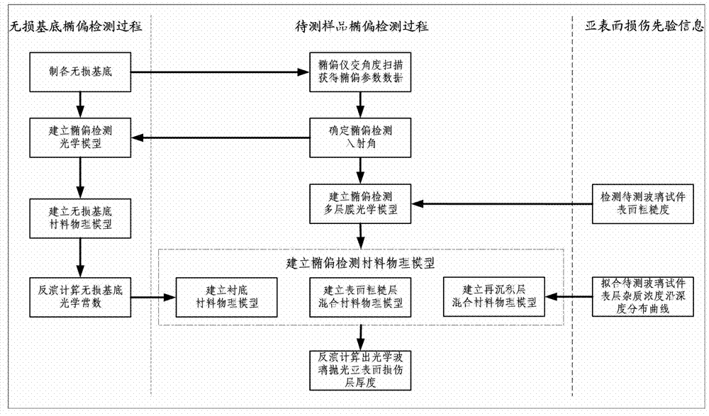
[0038] a kind of like figure 1 The nondestructive detection method of the optical glass polishing subsurface damage of the present invention shown, comprises the following steps:

[0039] (1) Preparation of non-destructive substrate: select Φ20mm×5mm quartz glass sample traditionally polished by cerium oxide as the glass sample to be tested; Liquid viscosity 350×10 -3 Pa s, using PF-1-1 cerium oxide polishing powder, current intensity 5A, polishing wheel speed 60r / min, flow rate 2L / min, magnetorheological polishing time 12h, the surface roughness after magnetorheological polishing was measured by atomic force microscope The Ra value is 0.359373nm; at 12°C, use 5% hydrofluoric acid to etch the sample after magnetorheological polishing for 3 minutes, and the etching depth is 59.6nm, which can effectively remove the subsurface mechanical damage and polishing redeposited substances left by traditional polishing. Get a lossless base;

[0040] (2) Determine the incident angle of ...

Embodiment 2

[0051] a kind of like figure 1 The nondestructive detection method of the optical glass polishing subsurface damage of the present invention shown, comprises the following steps:

[0052] (1) Preparation of non-destructive substrate: choose Φ20mm×5mm size and undergo rough magnetorheological polishing (using x-y scanning method, magnetorheological fluid viscosity 350×10 -3 Pa s, using PF-1-1 cerium oxide polishing powder, current intensity 6A, polishing wheel speed 80r / min, flow rate 31 / min, polishing time 2h) quartz glass sample as the glass sample to be tested; first use magnetorheological Polishing process The glass sample to be tested is polished, and the specific polishing parameters are the same as in Example 1. The surface roughness Ra value measured by an atomic force microscope is 0.370702nm; Sample 3min, etching depth 71nm, effectively remove subsurface mechanical damage and polishing re-deposited substances left by magnetorheological rough polishing, and obtain a n...


PUM

PropertyMeasurementUnit
Surface roughnessaaaaaaaaaa
Depthaaaaaaaaaa
Surface roughnessaaaaaaaaaa

Abstract

The invention discloses a non-destructive testing method for optical glass polishing sub-surface damages. The method comprises the following steps of: preparing a non-destructive base at first, and then determining an incident angle for ellipsometry detection; calculating the optical constant of the non-destructive base according to ellipsometry parameters measured with the incident angle for ellipsometry detection, wherein the non-destructive base is defined as a substrate-environment structure, and a standard dielectric function is taken as a material physical model; defining a sub-surface damage surface of a sample as a multi-film optical model which comprises air, a coarse surface layer, a resedimentation layer and a substrate; building a multi-film material physical model through a mixed material effective medium model based on the multi-film optical model, and measuring the surface roughness and the depth distribution rule of surface sedimentation substances of the sample by virtue of the optical constant of the non-destructive base; and finally, carrying out inverse operation by a regression algorithm according to the ellipsometry parameters of the sample measured with the incident angle for ellipsometry detection, thus obtaining the depth of the sub-surface damage layer. The testing method is accurate, reliable, quick, efficient, flexible and controllable.

Description

technical field [0001] The invention relates to a method for detecting damage on the surface of an optical element, in particular to a method for detecting damage depth on an optical glass polished subsurface Background technique [0002] The existence of subsurface damage directly reduces important performance indicators such as the service life, long-term stability, coating quality, imaging quality, and laser damage threshold of optical components, especially polished subsurface damage such as redeposited impurities, plastic scratches, and microcracks. It will cause fatal damage to optical components in the environment of strong laser and high energy concentration. The characteristic scales of the above-mentioned polished subsurface damage are small (the plastic scratches are at the nanometer scale, and the concentration of polishing impurities is at the ppm level), and the forms are diverse, and the mutual coupling is difficult to distinguish effectively (the redeposited ...

Claims


Application Information

Patent Timeline
IPC IPC(8): G01N21/958
Inventor 王卓杨军宏曹玉君徐小军尚建忠戴一帆李圣怡
Owner NAT UNIV OF DEFENSE TECH
Features
  • Generate Ideas
  • Intellectual Property
  • Life Sciences
  • Materials
  • Tech Scout
  • Unparalleled Data Quality
  • Higher Quality Content
  • 60% Fewer Hallucinations
Learn More