Low-cost solar electromagnetic power assisting bicycle

A technology of electromagnetic power assist and solar panels, applied in electric vehicles, electric braking systems, electrical components, etc., can solve the problems of complex pipeline structure, lack of road sense information, high energy consumption, etc., to achieve fun, superior performance, small performance effect

Active Publication Date: 2013-06-05
吴江科技创业园管理服务有限公司
View PDF5 Cites 11 Cited by
  • Summary
  • Abstract
  • Description
  • Claims
  • Application Information

AI Technical Summary

Problems solved by technology

[0003] In order to overcome the relatively high energy consumption of the existing mechanical hydraulic power assist system, the pipeline structure is very complicated, the number of various valves for controlling oil is large, and the system in the electric power steering system isolates the direct connection between people and the road surface, making the road feel Insufficient information, defects such as overshooting, in order to avoid many shortcomings of the two types of power steering systems, the present invention provides a low-cost solar-powered electromagnetic power-assisted bicycle, which uses an electromagnetic main force disc to realize steering power-assisted

Method used


Image

  • Low-cost solar electromagnetic power assisting bicycle
  • Low-cost solar electromagnetic power assisting bicycle
  • Low-cost solar electromagnetic power assisting bicycle

Examples


specific Embodiment approach

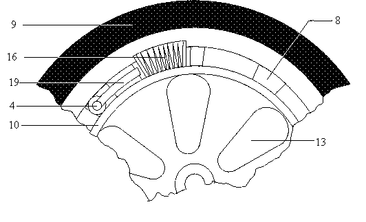
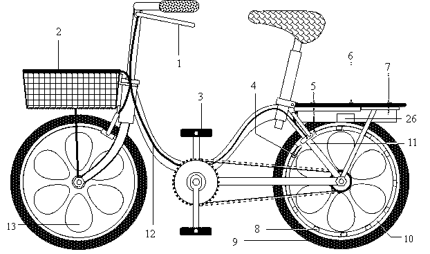
[0023] Example 1: The present invention consists of a bicycle shopping basket solar cover plate 2, a position sensor 4, an electromagnetic booster disc 5, a rear hanger solar panel 6, a booster permanent magnet 8, and a torque sensor 25; the position sensor 4 is located in front of the 5 electromagnetic booster discs , the distance between the two is equal to the distance between the two power-assisted permanent magnets 8 on the outer edge of the spoke plate 10, the torque sensor 25 is located on the central axis 21 of the bicycle, the torque signal and the orientation of the bicycle motion state by the torque signal induction coil 24 and the position sensor 4 The signal is transmitted to the electric control board 26, and the electric control board controls the electromagnetic booster disc 5 through the brake electric control combination line 12. After the solar cover plate 2 of the bicycle shopping basket and the solar panel 6 of the rear hanger are regulated by the voltage st...

example 1

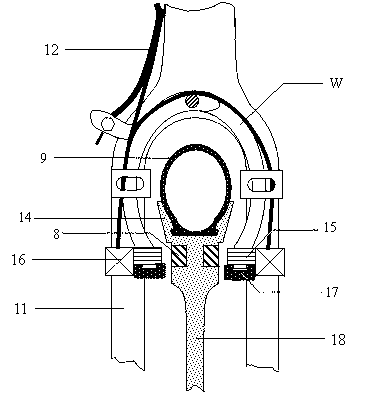
[0024] Electromagnetic booster disc 5 is made up of a pair of left and right booster electromagnets 15, corresponding booster electromagnet coils 16 and brake pads. The electromagnet is a U-shaped electromagnet. Outer casing, the power-assisted electromagnet coil 16 is wound around the central waist of the U-shaped electromagnet, and the bicycle brake pads are provided with dovetail grooves, which can be installed and fixed at the two ends of the U-shaped electromagnet. The entire electromagnetic booster disc 5 is installed at the original brake pad position to replace the original brake The left and right electromagnetic booster discs 5 are fixed on the brake handle brake 27 of the bicycle, the brake handle brake is installed on the seat stay 11 of the bicycle, and the electromagnet coil power supply line and the brake wire are merged into a bundle of brake electric control combination wires 12 (such as figure 2 As shown), a sensor fixing bracket 19 is installed and fixed on ...

example 2

[0026] Electromagnetic booster disc 5 is made up of a pair of left and right booster electromagnets 15, corresponding booster electromagnet coils 16 and brake pads. The electromagnet is a U-shaped electromagnet. Outer casing, the power-assisted electromagnet coil 16 is wound around the central waist of the U-shaped electromagnet, and the bicycle brake pads are provided with dovetail grooves, which can be installed and fixed at the two ends of the U-shaped electromagnet. The entire electromagnetic booster disc 5 is installed at the original brake pad position to replace the original brake The left and right electromagnetic booster discs 5 are fixed on the brake handle brake 27 of the bicycle, the brake handle brake is installed on the seat stay 11 of the bicycle, and the electromagnet coil power supply line and the brake wire are merged into a bundle of brake electric control combination wires 12 (such as figure 2 As shown), a sensor fixing bracket 19 is installed and fixed on ...


PUM


Abstract

The invention relates to a low-cost solar electromagnetic power assisting bicycle. The low-cost solar electromagnetic power assisting bicycle is composed of a bicycle shopping basket solar cover board 2, a position sensor 4, an electromagnetic power assisting plate 5, a rear luggage-carrier solar cell panel 6, a power assisting permanent magnet 8 and a torque sensor 25. A torque signal sensing coil 24 and the position sensor 4 transmit torque signals and bearing signals of bicycle movement states to an electric control board 26, the electric control board controls the electromagnetic power assisting plate 5 through a brake electric control assemble line 12, and the bicycle shopping basket solar cover board 2 and the rear luggage-carrier solar cell panel 6 provide power to a storage battery 7. According to the low-cost solar electromagnetic power assisting bicycle, a motor is not adopted, the power assisting system cannot change feelings of a rider, the solar cell panel is adopted to supply power, energy is saved, when the bicycle is braked, the electric power can be recycled automatically, and the labor energy of the rider is saved. The low-cost solar electromagnetic power assisting bicycle is a small and exquisite power assisting device which is excellent in performance, is extremely simple in structure, good in market prospect and free from discharging and has an extremely important value on bicycle popularization and usage.

Description

technical field [0001] The invention relates to a low-cost solar-powered electromagnetic power-assisted bicycle, which belongs to the technical field of vehicles. Background technique [0002] Current power-assisted bicycles fall into two categories, each with its own advantages and disadvantages. Electric bicycles use electricity, do not produce exhaust gas, and are environmentally friendly; fuel-powered bicycles burn oil to produce exhaust gas, which is not environmentally friendly. The disadvantage of electric bicycles is that the riding time is limited by the characteristics of the battery. At present, lead-acid batteries are mainly used, which have low energy storage density and limit the riding distance. After one year of use, the battery often needs to be charged every day. If you live upstairs , the electric moped is too heavy to carry upstairs. If it goes uphill, the power of the motor is generally insufficient and soft. If the power of the motor is increased, the ...

Claims


Application Information

Patent Timeline
Patent Type & Authority Applications(China)
IPC IPC(8): B62M6/40B62M6/85
CPCB60L7/10B60L2200/46B62M6/85H02J7/14H02J7/35
Inventor 陈蜀乔陈雨彤
Owner 吴江科技创业园管理服务有限公司
Why Eureka
Try Eureka