Supercharge Your Innovation With Domain-Expert AI Agents!

Static electricity optical fiber measurement appliance and measurement method

A technology for optical fiber measurement and static electricity, which is applied to electrostatic instruments, wire/needle electrometers, etc., to achieve the effect of simple operation, low loss and accurate acquisition

Active Publication Date: 2013-06-05
武汉东创黄冈海洋实业有限公司
View PDF4 Cites 6 Cited by
  • Summary
  • Abstract
  • Description
  • Claims
  • Application Information

AI Technical Summary

Problems solved by technology

[0002] The electrostatic optical fiber measuring instrument is a technology for measuring the static electricity generated by friction inside the vehicle fuel tank. At present, the technology applied to the static electricity of the vehicle fuel tank is very lacking. This kind of technology is mostly used in the measurement of the static electricity of the fuel tank of the aircraft. At present, the traditional method of measuring static electricity adopts the measurement method of insulation resistance R (resistivity ρ), electrostatic discharge constant τ and half-life τ 半 The measurement method of the electrostatic potential V, the measurement method of the electric quantity Q and the charge density σ, the light reflection method, the process is simple, but it is not used for the measurement of the static electricity inside the special automobile fuel tank.

Method used


Image

  • Static electricity optical fiber measurement appliance and measurement method
  • Static electricity optical fiber measurement appliance and measurement method
  • Static electricity optical fiber measurement appliance and measurement method

Examples


Embodiment 1

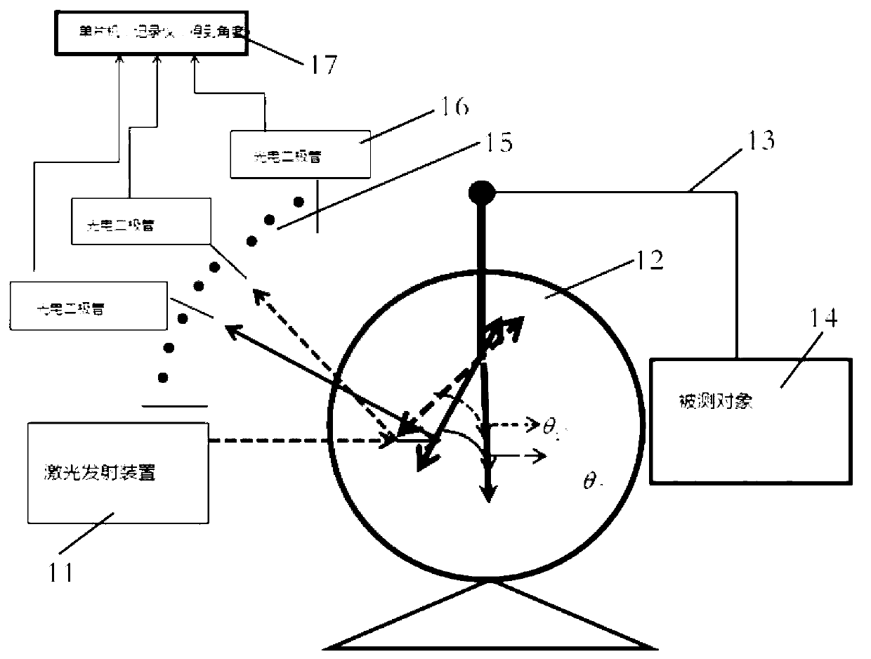
[0035] figure 1 It is a structural schematic diagram of Embodiment 1 of the present invention. In this embodiment, the light emitting device is a laser emitting device 11, the light receiving device is an optical fiber array 15, and the photoelectric conversion unit is a photodiode array 16, and each photodiode is respectively connected to The optical fibers in an optical fiber array are connected, and the arrangement of the optical fibers in the optical fiber array makes the optical fiber receiving the optical signal correspond to the opening angle θ of the coated electrostatic inspection device 12 . The positional relationship between the laser emitting device 11 and the coating electrostatic inspection device 12 is such that when the light emitted by the laser emitting device 11 is reflected on the coating electrostatic inspection device 12, the incident angle and reflection angle of the light are all separated from the coating electrostatic inspection device 12. The angle ...

Embodiment 2

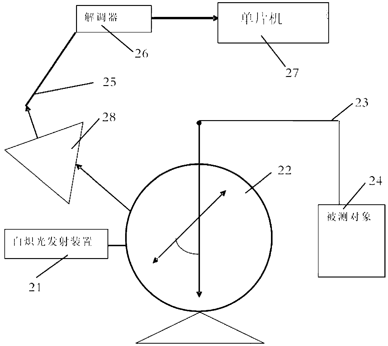
[0052] The principle and structure of this embodiment are basically the same as that of Embodiment 1, the difference is that: figure 2 As shown, the light emitting device is an incandescent lamp emitting device 21; the light receiving device includes a triangular prism 28 and an optical fiber array 25, and the triangular prism 28 is arranged between the optical fiber array 25 and the coating electrostatic inspection device 22 for refracting the reflected incandescent light into different spectra The light is received by the corresponding optical fiber in the optical fiber array 25, and the arrangement of the optical fiber in the optical fiber array makes the optical fiber that receives the optical signal correspond to the wavelength of the optical signal and the opening angle θ of the coating electrostatic inspection device; the photoelectric conversion unit is Fiber Bragg grating demodulator 26.

[0053] Such as Figure 5 As shown, the electrostatic optical fiber measuremen...


PUM


Abstract

The invention provides a static electricity optical fiber measurement appliance and a measurement method. The static electricity optical fiber measurement appliance comprises a light emitting device, a coating film static electricity test device, a light receiving device, a photovoltaic conversion unit and a single chip microcomputer. The coating film static electricity test device is connected with a tested object through static electricity conducting wires to collect static electricity amount of the tested object. The coating film static electricity device opens at an angle theta after receiving the static electricity amount. Light sent out through the light emitting device is lit on the coating film static electricity device, is received by the light receiving device after being reflected and is converted into an electric signal and sent to the single chip microcomputer through the photovoltaic conversion unit. According to the static electricity optical fiber measurement appliance and the measurement method, the opening degree caused by that the coating film static electricity test device receives static electricity is ingeniously combined with a light reflection principle, and therefore the static electricity amount of the tested object is calculated. Due to the fact that loss in the two process of opening the coating film static electricity test device at a certain degree after the coating film static electricity test device receives static electricity and light reflection is very small, the electricity amount in the inner portion of an oil tank is accurately obtained, and the operation is simple.

Description

technical field [0001] The invention belongs to a device for indicating the amount of static electricity, which is used to measure the amount of static electricity generated by friction inside the inner box of a vehicle. Background technique [0002] The electrostatic optical fiber measuring instrument is a technology for measuring the static electricity generated by friction inside the vehicle fuel tank. At present, the technology applied to the static electricity of the vehicle fuel tank is very lacking. This kind of technology is mostly used in the measurement of the static electricity of the fuel tank of the aircraft. At present, the traditional method of measuring static electricity adopts the measurement method of insulation resistance R (resistivity ρ), electrostatic discharge constant τ and half-life τ 半 The measurement method, the measurement method of electrostatic potential V, the measurement method of electric quantity Q and charge density σ, the light reflection...

Claims


Application Information

Patent Timeline
IPC IPC(8): G01R5/32
Inventor 吕植勇何荣李木明张琴兰黄思俊付姗姗刘湘易俊威倪林轩
Owner 武汉东创黄冈海洋实业有限公司
Features
  • R&D
  • Intellectual Property
  • Life Sciences
  • Materials
  • Tech Scout
  • Unparalleled Data Quality
  • Higher Quality Content
  • 60% Fewer Hallucinations
Learn More