Optical information reproducing apparatus

一种信息再生、光信息的技术,应用在信息存储、记录信息存储、光束源等方向,能够解决S/N比降低等问题

Active Publication Date: 2013-06-05
HITACHI MEDIA ELECTORONICS CO LTD
View PDF6 Cites 4 Cited by
  • Summary
  • Abstract
  • Description
  • Claims
  • Application Information

AI Technical Summary

Problems solved by technology

[0006] However, in the above-mentioned Patent Document 1, 16 detectors are required for the reproduced signal and the focus error signal with a high S / N ratio generated by the interference light between the signal light and the reference light, and the number of detectors is very large. As a result, , the S / N ratio decreases due to the influence of amplifier noise and shot noise

Method used


Image

  • Optical information reproducing apparatus
  • Optical information reproducing apparatus
  • Optical information reproducing apparatus

Examples


Embodiment 1

[0127] In Embodiment 1, an example in which defocusing of a different sign is performed with respect to the reference light will be described.

[0128] [Structure of optical system of optical pickup]

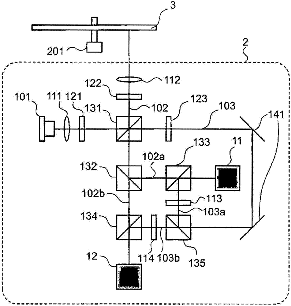
[0129] figure 1 A schematic diagram showing the optical system of the optical pickup 2 for realizing the optical signal detection method of the present invention. The optical pickup optical system of this embodiment is composed of the following parts: an interference optical system for guiding light emitted from a semiconductor laser to an optical disk and reflecting it, and interfering the reflected light (signal light) with reference light to generate interference light ; The detection optical system is used to separate the generated interference light, give the separated interference light a phase difference and detect it through a plurality of detectors.

[0130]

[0131] The light emitted from the semiconductor laser 101 becomes parallel light through the collimator len...

Embodiment 2

[0269] In an embodiment, as figure 1 As shown, the first reference light 103a and the second reference light 103b are given defocusing with different signs by the first lens 113 and the second lens 114, but as other embodiments of the present invention, as Figure 10 As shown, the first signal light 102a and the second signal light 102b may be defocused with different signs. for Figure 10 In the optical pickup 2 of , the already explained figure 1 The parts with the same symbols and the parts having the same functions are shown, and the description is omitted.

[0270] The reference light 103 that has passed through the λ / 2 plate 121 and passed through the polarized beam splitter 131 is converted into vertically polarized light by the λ / 2 plate 123 as described above, reflected by the reference light reflection unit 141, and passed through the beam splitter. 135 is separated into the first reference light 103a and the second reference light 103b, and faces the detection op...

Embodiment 3

[0272] In Embodiment 1 or 2, the first lens 113 and the second lens 114 are used as means for defocusing the above-described first or second light beams in the front and rear, but a curved diffraction grating may also be used. The curved diffraction grating is a grating obtained by cutting the center of a so-called Fresnel zone plate, which is arranged in a concentric shape and whose pitch becomes thinner at the periphery, and which is an effect of the Fresnel zone plate. Diffracted light produces a lens effect. This lens action has opposite directions for the +1st-order diffracted light and the -1st-order diffracted light, and if the +1st-order diffracted light produces a convex lens action, the -1st-order diffracted light produces a concave lens action. Conversely, if the concave lens action is produced for the +1st-order diffracted light, the convex lens action is produced for the -1st-order diffracted light. As a result, it is possible to form a light beam whose focus is ...


PUM

PropertyMeasurementUnit
wavelengthaaaaaaaaaa
pore sizeaaaaaaaaaa
diameteraaaaaaaaaa

Abstract

Disclosed is an optical information reproducing apparatus that has a light path difference between two lights easily adjusted, has a high effect on the amplification of a signal, and detects an optical information signal of an interfering type. The optical information reproducing apparatus splits a luminous flux emitted from a laser source into a first luminous flux as a signal light and a second luminous flux as a reference light not collected on an optical information recoding medium, makes the signal light optically interfere with the reference light in a state in which the signal light and the reference light are different from each other in a phase relationship to thereby produce interfering lights, and detects the interfering lights.

Description

technical field [0001] The present invention relates to an information reproducing device for reproducing information by irradiating light onto an information recording medium. Background technique [0002] For optical discs, Blu-ray discs (BD) using a cyan semiconductor laser and a high NA objective lens of NA0.85 have already been commercialized, and the resolution of the optical system has almost reached the limit. Multilayering of layers is competitive. In recent years, Blu-ray Discs having 2 to 3 recording layers are on the market, and are used as image storage media for recorders and data storage media for personal computers. [0003] In such a multi-layer optical disk, the amount of light to be detected from each recording layer must be approximately equal, and therefore the reflectance of each recording layer must be reduced as the number of recording layers increases. Therefore, there is a problem that the S / N ratio of the detection signal from each recording laye...

Claims


Application Information

Patent Timeline
Patent Type & Authority Applications(China)
IPC IPC(8): G11B7/13G11B7/126G11B7/1392
CPCG11B7/005G11B7/0917
Inventor 井手达朗
Owner HITACHI MEDIA ELECTORONICS CO LTD
Why Eureka
Try Eureka