
Passive wireless pressure sensor based on flexible substrates

A pressure sensor, passive wireless technology, applied in the field of sensors, can solve the problems of limiting the overall characteristics of the device, difficult to obtain quality factor, difficult to batch process, etc., to achieve the effect of high quality factor Q value, low loss and low power consumption

Inactive Publication Date: 2013-06-12
SOUTHEAST UNIV
View PDF7 Cites 15 Cited by
  • Summary
  • Abstract
  • Description
  • Claims
  • Application Information

AI Technical Summary

Problems solved by technology

The inductance can be an on-chip inductance integrated with a capacitive sensor, but it is generally difficult to obtain a high quality factor Q for this inductance, thereby limiting the overall characteristics of the device; in addition, an externally wound metal wire inductance coil can also be used. But this will increase the size of the device, and it is difficult to process in batches
In addition, MEMS pressure-sensitive capacitors also need to solve two major technical difficulties: the lead wire of the capacitor plate and the sealing of the cavity

Method used


Image

  • Passive wireless pressure sensor based on flexible substrates
  • Passive wireless pressure sensor based on flexible substrates
  • Passive wireless pressure sensor based on flexible substrates

Examples


Embodiment Construction

[0020] The technical solution of the present invention will be described in further detail below in conjunction with the accompanying drawings and embodiments.

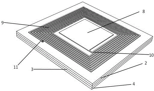
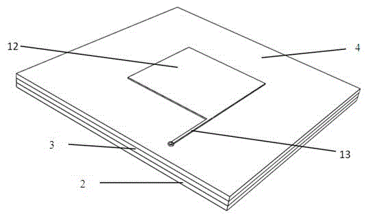
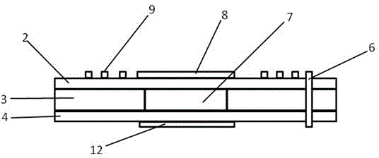
[0021] Such as Figure 1 to Figure 4 As shown, a passive wireless pressure sensor based on a flexible substrate of the present invention includes an upper metal layer 1, an upper flexible substrate 2, a middle flexible substrate 3, a lower flexible substrate 4 and a lower Metal layer 5. The upper flexible substrate 2, the middle flexible substrate 3 and the lower flexible substrate 4 are all made of flexible materials, such as polyimide (PI), liquid crystal polymer (LCP), or polyethylene terephthalate. Alcohol esters (PET). The upper flexible substrate 2 , the middle flexible substrate 3 and the lower flexible substrate 4 are provided with electrical vias which communicate with each other. That is to say, the electrical via hole passes through the upper flexible substrate 2 , the middle flexible substrate 3 and the...


PUM

PropertyMeasurementUnit
thicknessaaaaaaaaaa

Abstract

The invention discloses a passive wireless pressure sensor based on flexible substrates. The passive wireless pressure sensor comprises an upper metal layer, an upper flexible substrate, a middle flexible substrate, a lower flexible substrate and a lower metal layer, wherein interlinked electrical through holes are formed in the upper flexible substrate, the middle flexible substrate and the lower flexible substrate; a cavity is formed on the middle flexible substrate; the upper metal layer comprises a planar inductance coil and a capacitive upper electrode plate which is arranged on the middle part of the planar inductance coil; an inner-side connecting head of the planar inductance coil is connected with the capacitive upper electrode plate; the lower metal layer comprises a capacitive lower electrode plate and an interconnecting wire, wherein the dimension of the capacitive lower electrode plate is the same as that of the capacitive upper electrode plate, the position of the capacitive lower electrode plate is opposite to that of the capacitive upper electrode plate, and the interconnecting wire is connected with the capacitive lower electrode plate; an outer-side connecting head of the planar inductance coil of the upper metal layer is connected with the interconnecting wire of the lower metal layer by a conductive medium column which is arranged in the electrical through holes; and the cavity of the middle flexible substrate is arranged between the capacitive upper electrode plate and the capacitive lower electrode plate. The pressure sensor has the excellent performances of non-contact, high flexibility, high quality factor and low power consumption.

Description

technical field [0001] The invention belongs to the technical field of sensors, and in particular relates to a passive wireless pressure sensor based on a flexible substrate. Background technique [0002] Pressure sensors are widely used in many occasions. In some special applications, such as: inside the human body, food packaging and other sealed environments, pressure sensors are required to have wireless telemetry capabilities. There are currently two types of wireless telemetry pressure sensors: active telemetry and passive telemetry. Active telemetry means that the sensing system has a power source. This type of telemetry can transmit sensor signals in both directions over long distances, but the system is complex, large in size, and the battery needs to be replaced. Passive telemetry means that there is no power source in the sensing system, and signals are acquired by using inductive coupling or radio frequency (RF) reflection modulation. This telemetry method has a...

Claims


Application Information

Patent Timeline
Patent Type & Authority Applications(China)
IPC IPC(8): G01L1/14
Inventor 陈洁张聪王立峰佘德群
Owner SOUTHEAST UNIV
Learn More