Drill bit with low chisel edge

A chisel edge and drill bit technology, used in the field of high-efficiency high-speed precision tools and low chisel edge drill bits, can solve problems such as delamination and exit burrs, and achieve the effects of reducing material delamination, suppressing runout, and improving heat dissipation capacity.

Active Publication Date: 2013-06-19
SUZHOU AHNO PRECISION CUTTING TECH CO LTD
View PDF6 Cites 14 Cited by
  • Summary
  • Abstract
  • Description
  • Claims
  • Application Information

AI Technical Summary

Problems solved by technology

[0003] The purpose of the present invention is to overcome the deficiencies in the prior art and provide a low chisel drill bit, which aims to solve t

Method used


Image

  • Drill bit with low chisel edge
  • Drill bit with low chisel edge
  • Drill bit with low chisel edge

Examples


Embodiment Construction

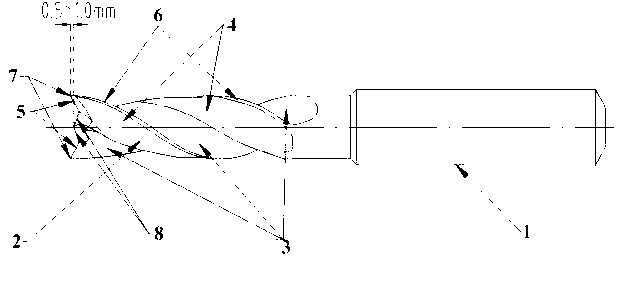
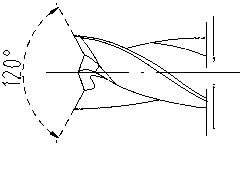
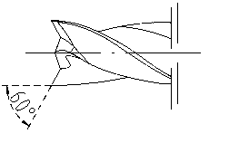
[0023] The design concept of the low-chisel drill bit of the present invention is to improve the sharpness of the drill bit, change the traditional processing method in which the chisel edge of the drill bit touches the workpiece first, and change the traditionally designed convex angle into a 120° inner concave angle to avoid radial force when drilling. A protective sipe with a negative rake angle is used at the rear end of the drill to improve the stability of the guide and reduce the secondary cutting of the workpiece by the edge of the drill, thereby inhibiting the tendency of the workpiece to produce arches and burrs.

[0024] Such as figure 1 As shown, the low chisel drill bit includes a shank 1 and a head 2, the shank 1 is a cylinder, the head 2 is a coaxial cylinder coaxial with the shank, and there are two rows on the head The chip flute 3, the solid part forming the chip flute is the tool back 4, the intersection line of the two chip flutes 3 and the tool back 4 in t...


PUM

PropertyMeasurementUnit
Widthaaaaaaaaaa

Abstract

The invention relates to a drill bit with a low chisel edge. The drill bit comprises a handle portion and a head portion, wherein the handle portion is a cylinder, the head portion is a coaxial cylinder which shares the same axis with the handle portion, two chip discharge grooves are formed in the head portion, a solid portion forming the chip discharge grooves is a knife back, intersecting lines of the two chip discharge grooves and the knife back in the axis direction respectively form two main cutting edges, intersecting lines of the two chip discharge grooves and the knife back in the radial direction form seamed edges, the seamed edges and the main cutting edges intersect to form a knife point, the chisel edge with 140-degree convexity is arranged between the two main cutting edges, and a sharp point of the chisel edge is 0.5-1mm lower than the knife point in the axis direction. Due to the chisel edge with the 140-degree convexity, knife strength is guaranteed, and meanwhile prominent centring capacity is guaranteed; the powerful centring capacity can inhibit bouncing and thereby guarantees long service life of a knife; and the drill bit is suitable for drilling machining for carbon fiber composite materials used for aviation.

Description

technical field [0001] The invention relates to high-efficiency, high-speed precision cutting tools, in particular to a low chisel drill bit used for processing aviation carbon fiber composite materials, and belongs to the technical field of optical-mechanical-electrical integration processing. Background technique [0002] The processing of aviation carbon fiber composite materials is still a difficult point in the field of aviation manufacturing. Especially in hole processing, manufacturing defects such as arching, material delamination, and export burrs are prone to occur, which will lead to parts scrapping in severe cases. At present, due to its balanced physical properties, high toughness and wear resistance, cemented carbide is still the main tool material in the processing of aviation carbon fiber composite materials. However, how to increase the rigidity of the drilling process and reduce the cutting resistance by improving the geometric angle of the tool, and then a...

Claims


Application Information

Patent Timeline
IPC IPC(8): B23B51/02
Inventor 刘伟王弢蒋长青
Owner SUZHOU AHNO PRECISION CUTTING TECH CO LTD
Why Eureka
Try Eureka