
Combined power generating system based on waste-heat utilization of combustion motor

A technology of combined power generation and internal combustion engine, applied in the direction of internal combustion piston engine, charging system, combustion engine, etc., can solve the problems of difficulty in application, large heat exchange temperature difference of heat exchanger, large irreversible loss, etc., to improve the utilization efficiency of waste heat. Effect

Inactive Publication Date: 2013-06-19
XI AN JIAOTONG UNIV
View PDF10 Cites 36 Cited by
  • Summary
  • Abstract
  • Description
  • Claims
  • Application Information

AI Technical Summary

Problems solved by technology

[0009] For the above-mentioned prior art, the organic Rankine cycle uses the waste heat of the flue gas of the internal combustion engine, and the heat exchange temperature difference in the heat exchanger is large, resulting in a large irreversible loss; the steam power cycle using water as the working medium or the cycle using water as the cold source It is difficult to apply in some water-scarce areas in the north

Method used


Image

  • Combined power generating system based on waste-heat utilization of combustion motor
  • Combined power generating system based on waste-heat utilization of combustion motor
  • Combined power generating system based on waste-heat utilization of combustion motor

Examples


Embodiment Construction

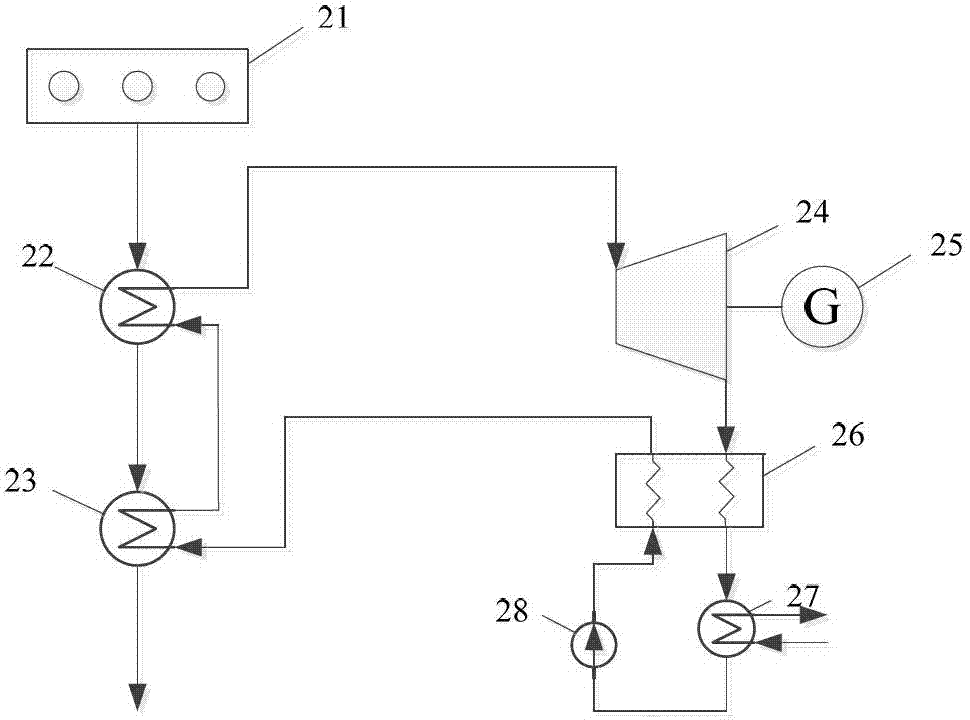
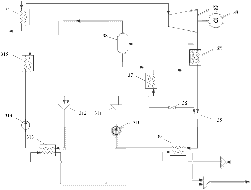
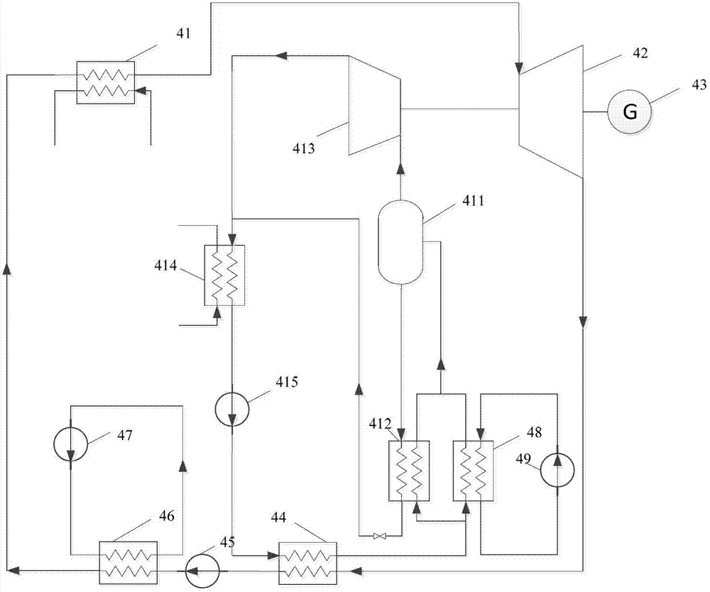
[0032] Figure 5 It is a flow chart of a combined power generation system based on the utilization of waste heat of an internal combustion engine according to the present invention. The system consists of an internal combustion engine 1, a first generator 2, a heater 3, a gas turbine 4, a second generator 5, a cooler 6, a compressor 7, an organic working fluid turbine 8, a third generator 9, a condenser 10. It consists of a booster pump 11, an evaporator 12, and a preheater 13. The system is composed of Brayton cycle and organic Rankine cycle. Brayton cycle is selected as the top cycle and CO 2 As the working fluid, the organic Rankine cycle is used as the bottom cycle, and R123, R113, R245fa, isopentane, etc. can be selected as working fluids. The combined cycle power generation system is used to realize the cascade recovery and utilization of the waste heat of the internal combustion engine. In addition, the internal combustion engine uses LNG as fuel. In order to utilize ...


PUM


Abstract

The invention discloses a combined power generating system based on waste-heat utilization of a combustion motor. The combined power generating system based on waste-heat utilization of the combustion motor is composed through combination of Bretton cycle and organic Rankine cycle. The combined power generating system based on waste-heat utilization of the combustion motor mainly comprises a gas turbine, a heat exchanger, a gas compressor, a turbine, a condenser, a booster pump and a circulating pump. Waste gas of the combustion motor firstly passes through a heater and transfers heat to carbon dioxide of Bretton cycle, carbon dioxide steam at the high temperature and the high pressure is formed to drive the gas turbine to generate power. The waste gas of the combustion motor still has high heat after passing through the heater, then the heat is transferred to an organic working medium in Rankine cycle through an evaporator, and organic working medium steam at the high temperature and the high pressure is formed. Carbon dioxide discharged from the gas turbine passes through a cooler, and heat of the carbon dioxide is transferred to the organic working medium in the Rankine cycle too, and organic working medium steam at the high temperature and the high pressure is formed. The turbine with the organic working medium is driven to generate power by two blasts of organic working medium steam at the high temperature and the high pressure.

Description

【Technical field】 [0001] The invention belongs to the field of high temperature and medium and low temperature heat energy recovery and power engineering, and relates to a combined power generation system based on the utilization of waste heat of an internal combustion engine. 【Background technique】 [0002] The heat taken by the exhaust gas when the internal combustion engine is running accounts for about 35% of the heat released by the complete combustion of the fuel, and currently this part of the heat is dissipated in the form of waste heat. Recovering this part of the waste heat from the exhaust gas of the internal combustion engine can save energy and reduce consumption. At present, there are the following Several technical solutions to recycle the waste heat of internal combustion engines: [0003] 1. Organic Rankine Cycle (ORC): Organic Rankine Cycle is a cycle that replaces the water working medium in the traditional steam Rankine cycle with an organic working mediu...

Claims


Application Information

Patent Timeline
IPC IPC(8): F02G5/02F01K23/02F02M21/06F02C1/05F02C1/10F01K25/10
CPCY02P80/15Y02T10/12Y02T10/30
Inventor 王江峰夏家曦王建永赵攀王漫戴义平
Owner XI AN JIAOTONG UNIV
Learn More