
Switching power supply, control method of switching power supply and control chip

A technology of switching power supply and control method, which is applied in the direction of control/regulation system, electrical components, and adjustment of electrical variables, etc., which can solve the problems of large standby power consumption, reduced energy density and low efficiency of switching duty cycle, and achieve high conversion efficiency , low power consumption, simple circuit effect

Active Publication Date: 2013-06-19
BYD SEMICON CO LTD
View PDF3 Cites 30 Cited by
  • Summary
  • Abstract
  • Description
  • Claims
  • Application Information

AI Technical Summary

Problems solved by technology

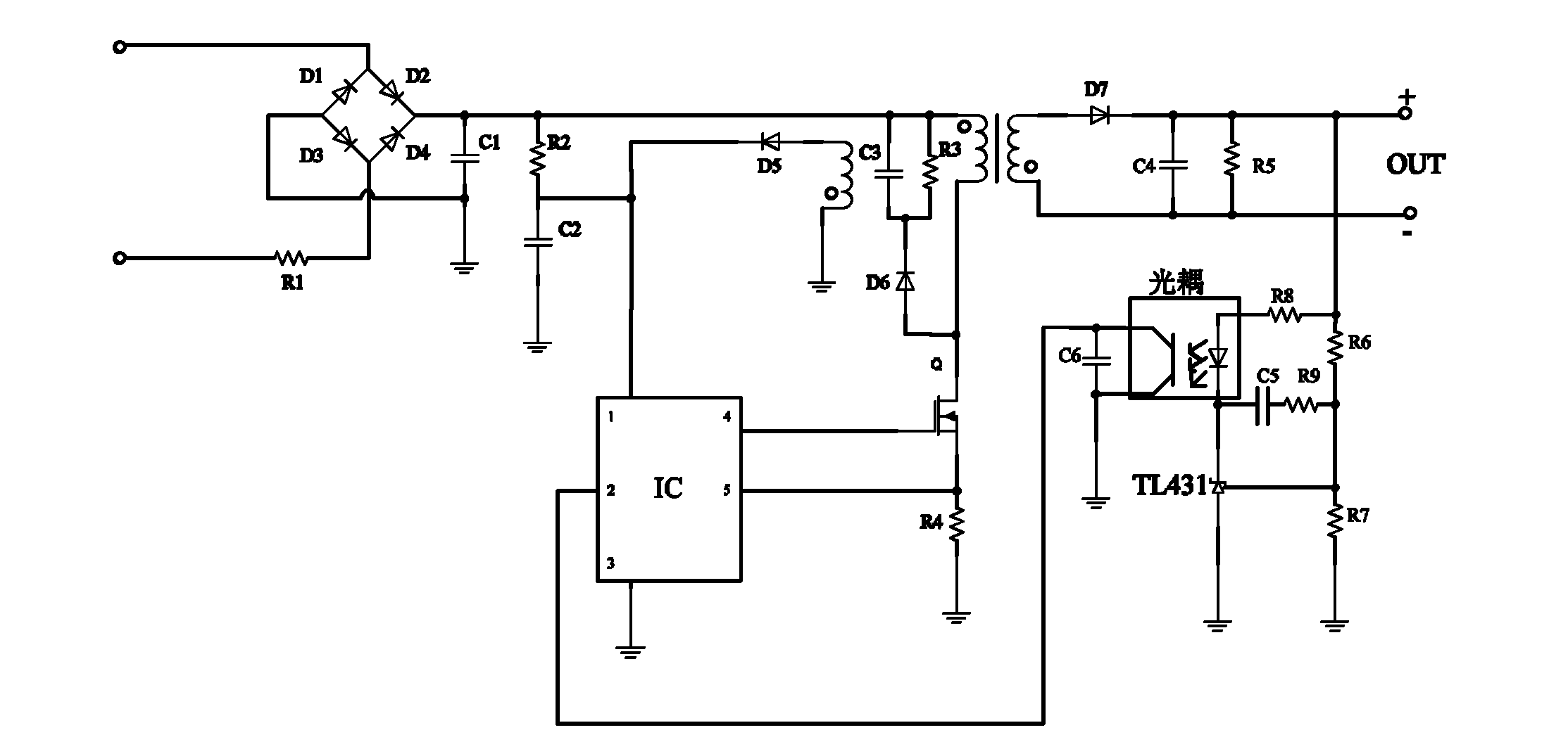
However, there is a problem with this switching power supply. Since the operating current required by the optocoupler and operational amplifier TL431 is above 1mA, it brings a large standby power consumption to the entire circuit system.
[0003] In the prior art, pulse width modulation PWM (Pulse Width Modulation) is usually used to control figure 1 The traditional secondary feedback control switching power supply shown in the figure is controlled. This control method can meet the output voltage requirements of the switching power supply, but the problem is that the efficiency is low under light load conditions.
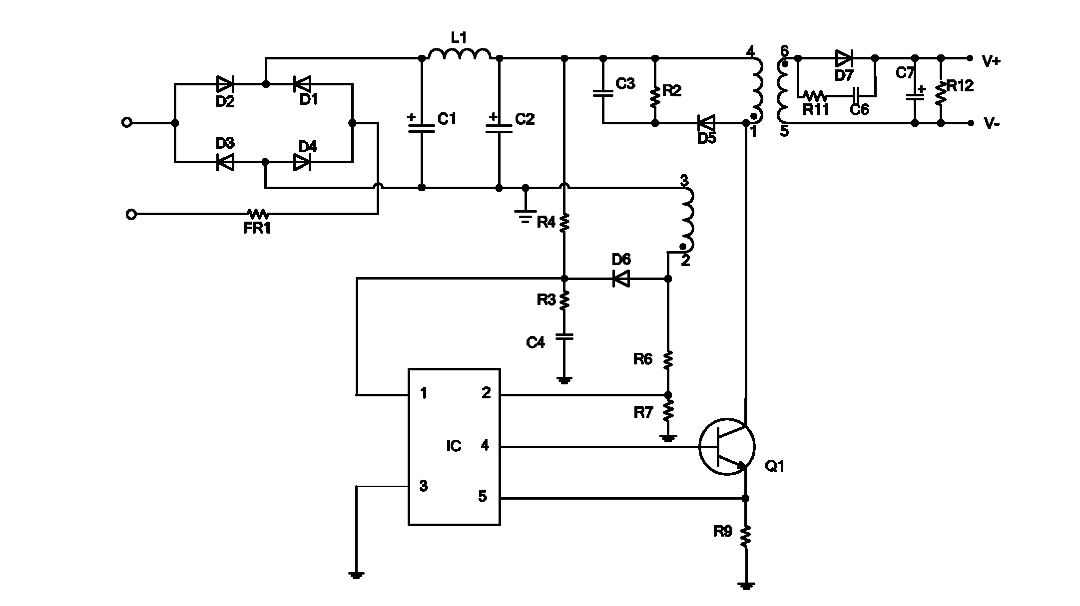
The output voltage is transmitted to the inside of the control chip IC after being coupled by the secondary winding of the transformer and the auxiliary winding and divided by resistors R6 and R7. The control chip IC controls the conduction time or operating frequency of the power transistor Q1 according to the output voltage collected. To achieve the stability of the output voltage, however, this switching power supply has the following problems. On the one hand, the energy transfer method of this flyback topology is that the DC input voltage charges the primary inductor when the power transistor Q1 is turned on, and the primary inductor is charged when the power transistor Q1 is turned off. The energy on the inductance is transferred to the secondary, and the detection of the output voltage can only occur within the secondary degaussing time, that is, the interval detection method is adopted. In order to meet the efficiency of the switching power supply within the full load range, it must be controlled simultaneously according to different load states. Switching duty cycle and operating frequency, on the other hand, before the switching frequency drops to the audio frequency range, the switching duty cycle must be reduced to a lower level in advance to reduce energy density and shield audio noise

Method used


Image

  • Switching power supply, control method of switching power supply and control chip
  • Switching power supply, control method of switching power supply and control chip
  • Switching power supply, control method of switching power supply and control chip

Examples


Embodiment Construction

[0027] Embodiments of the present invention are described in detail below, examples of which are shown in the drawings, wherein the same or similar reference numerals designate the same or similar elements or elements having the same or similar functions throughout. The embodiments described below by referring to the figures are exemplary only for explaining the present invention and should not be construed as limiting the present invention.

[0028] The following disclosure provides many different embodiments or examples for implementing different structures of the present invention. To simplify the disclosure of the present invention, components and arrangements of specific examples are described below. Of course, they are only examples and are not intended to limit the invention. Furthermore, the present invention may repeat reference numerals and / or letters in different instances. This repetition is for the purpose of simplicity and clarity and does not in itself indicat...


PUM


Abstract

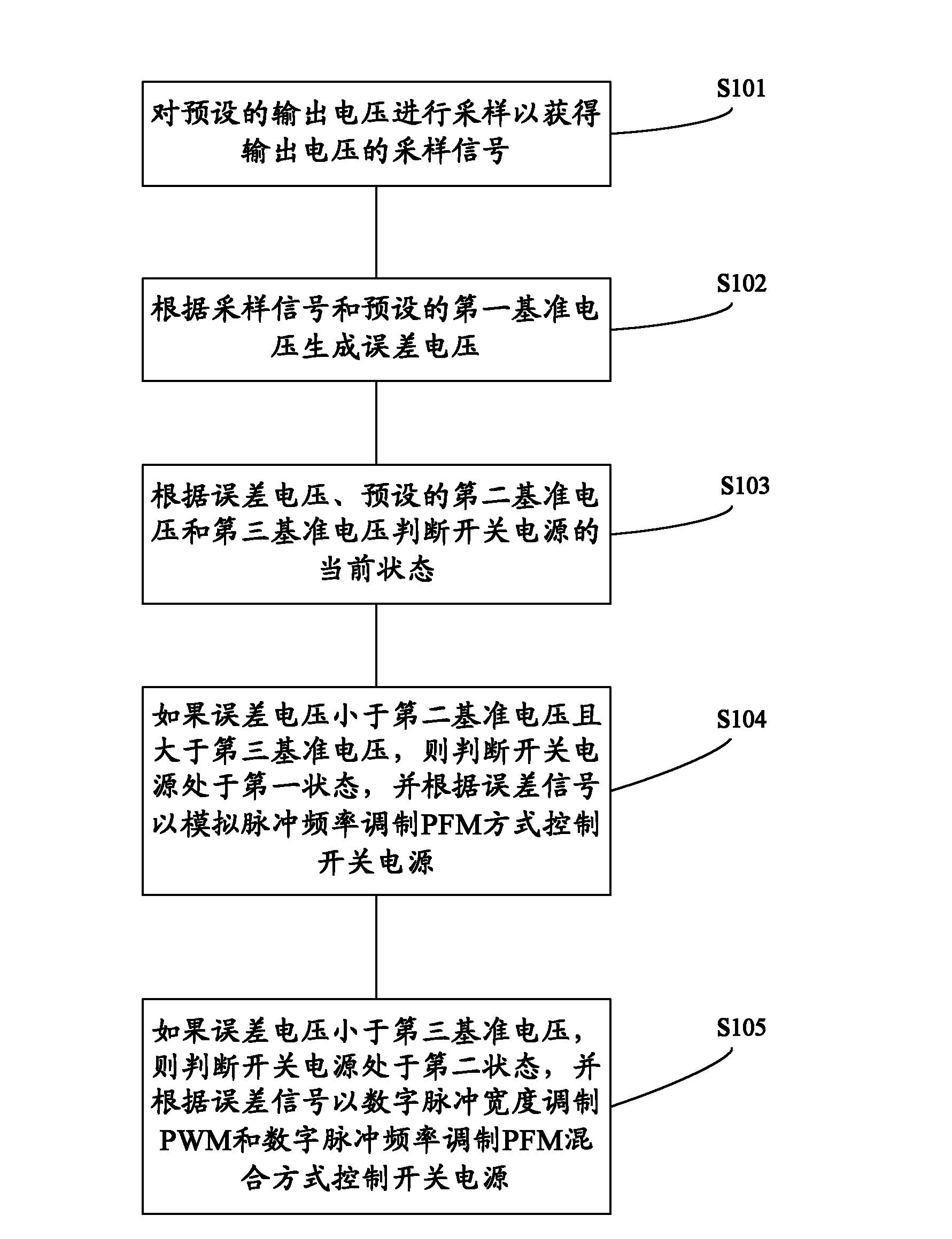
The invention provides a switching power supply, a control method of the switching power supply and a control chip. The control method of the switching power supply comprises the following steps: sampling preset output voltages to acquire sampling signals; generating an error voltage according to the sampling signals and a first reference voltage; judging a current state of the switching power supply according to the error voltage, a preset second reference voltage and a third reference voltage; if the error voltage is smaller than the second reference voltage and larger than the third reference voltage, and then the switching power supply is in a first state, and controlling the switching power supply according to the error voltage in a simulated pulse frequency modulation (PFM) mode; if the error voltage is smaller than the third reference voltage, and then the switching power supply is in a second state, and controlling the switching power supply according to the error voltage in a mixed mode of digital pulse width modulation (PWM) and digital PFM. The control method of the switching power supply can meet high accuracy of the output voltage of the switching power supply, and has high conversion efficiency in a full load range, and therefore dynamic response speed of the switching power supply is improved, and voice frequency noise in a light load state can be avoided.

Description

technical field [0001] The invention relates to the technical field of switching power supplies, in particular to a switching power supply, a control method thereof, and a control chip. Background technique [0002] With the increasing awareness of environmental protection and energy saving, countries have stricter requirements on the working efficiency of power adapters and built-in power supplies in AC equipment. Such as figure 1 Shown is the circuit diagram of a switching power supply with traditional secondary feedback control. In order to meet the requirements of precision and isolation safety, the traditional secondary feedback control circuit is equipped with an optocoupler and an operational amplifier ( figure 1 TL431 shown), the output voltage is divided by resistors R6 and R7 and then transmitted to the operational amplifier TL431 for amplification processing, and then the amplified output voltage signal is transmitted to the voltage sampling terminal 2 of the chi...

Claims


Application Information

Patent Timeline
Patent Type & Authority Applications(China)
IPC IPC(8): H02M3/335H02M1/08H02H7/20
Inventor 杨小华叶文辉
Owner BYD SEMICON CO LTD
Learn More