On-orbit polarization measuring system of satellite-borne imaging spectrometer

An imaging spectrometer and measurement system technology, applied in the field of space optics, can solve the problems of reducing imaging quality, measurement accuracy error, etc., and achieve the effects of improving measurement accuracy, simple structure, and light weight

Inactive Publication Date: 2013-06-26
CHANGCHUN INST OF OPTICS FINE MECHANICS & PHYSICS CHINESE ACAD OF SCI
View PDF0 Cites 6 Cited by
  • Summary
  • Abstract
  • Description
  • Claims
  • Application Information

AI Technical Summary

Problems solved by technology

[0003] The present invention provides an on-orbit polarization measurement system for spaceborne imaging spectrometers in order to solve the problem that the measurement accuracy of existing

Method used


Image

  • On-orbit polarization measuring system of satellite-borne imaging spectrometer
  • On-orbit polarization measuring system of satellite-borne imaging spectrometer

Examples


specific Embodiment approach 1

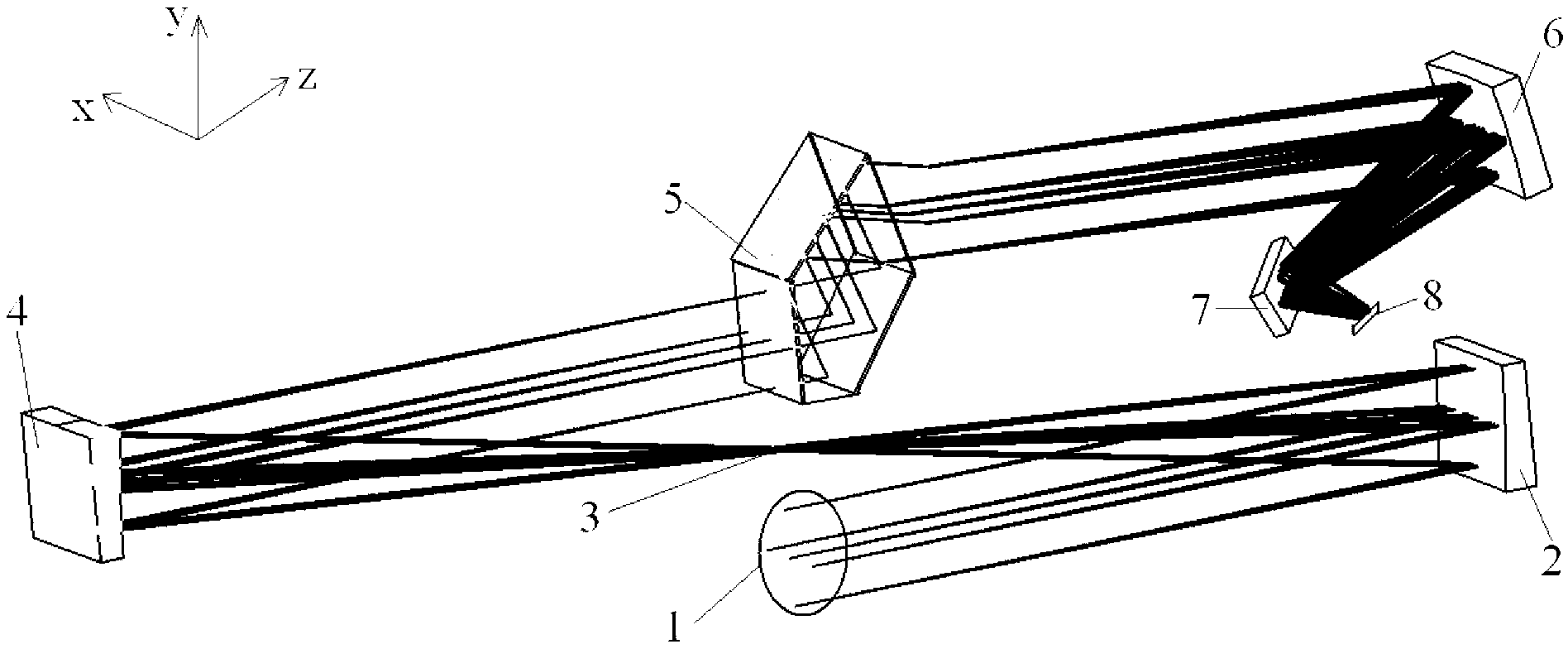
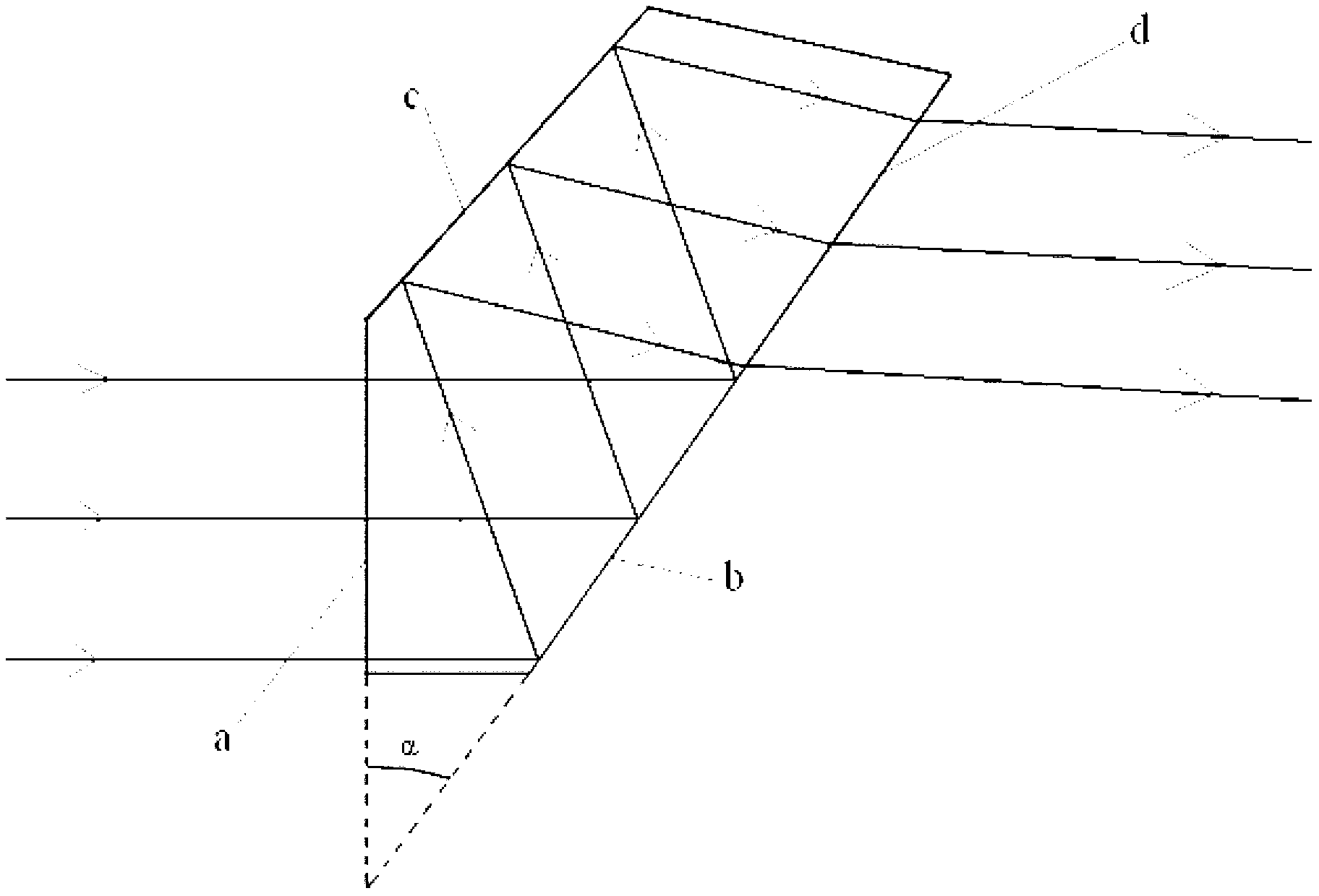
[0010] Specific implementation mode 1. Combination figure 1 and figure 2 Description of the present embodiment, an on-orbit polarization measurement system of a spaceborne imaging spectrometer, uses Brewster prism 5 as a light splitting and polarization element to realize on-orbit polarization measurement of a spaceborne imaging spectrometer; the system includes an aperture stop 1, Telescope 2, entrance slit 3, collimating mirror 4, Brewster prism 5, focusing mirror 6, plane folding mirror 7 and focal plane detector 8. The system is arranged in an orderly manner according to the xyz right-handed space coordinate system, the z-axis direction is defined as the optical axis direction, the x-axis is perpendicular to the yz plane, the yz plane is the meridian plane of the system, the length direction of the incident slit 3 is along the x-axis direction, and the incident slit 3 is along the x-axis direction. The slit width direction is along the y-axis direction. The incident lig...

specific Embodiment approach 2

[0015] Specific Embodiment 2. This embodiment is an embodiment of the on-orbit polarization measurement system of a spaceborne imaging spectrometer described in Specific Embodiment 1:

[0016] The on-orbit polarization measurement system of the spaceborne imaging spectrometer described in this embodiment is used in conjunction with the imaging spectrometer for atmospheric detection to measure the polarization characteristics of incident light, thereby correcting the polarization response of the imaging spectrometer. The working band of the on-orbit polarization measurement system of the spaceborne imaging spectrometer is 320-500nm, and the atmospheric scattered light radiation with a field angle of 1.8°×0.045° is imaged on the incident slit through the aperture diaphragm and off-axis parabolic telescope. The diameter of the aperture is Φ31mm, the focal length of the off-axis parabolic telescope is 240.269mm, the off-axis distance is 35mm, the size of the incident slit is 7.55mm...


PUM


Abstract

The invention discloses an on-orbit polarization measuring system of a satellite-borne imaging spectrometer, and relates to the technical field of space optics. The on-orbit polarization measuring system solves the problem of deterioration of imaging quality due to a depolarization instrument of an existing satellite-borne imaging spectrometer. The on-orbit polarization measuring system comprises an aperture diaphragm, a telescope, an entrance slit, a collimating lens, a Brewster prism, a focus lens, a plane turning mirror and a focal plane detector. An aiming beam enters the telescope via the aperture diaphragm, and is imaged on the entrance slit via the telescope, light which exits from the entrance slit enters the Brewster prism after being collimated by the collimating lens, S-polarized light enters the focus lens after being subjected to chromatic dispersion and polarizing beam splitting by the Brewster prism, is focused by the focus lens, is turned by the plane turning mirror and then is imaged on the area focal plane detector, and the vibration direction of the S-polarized light is parallel to the length direction of the slit. The on-orbit polarization measuring system is applicable to meeting requirements of space remote sensing atmospheric sounding and ocean color exploration.

Description

technical field [0001] The invention relates to the field of space optics technology, in particular to an on-orbit polarization measurement system for a spaceborne imaging spectrometer. Background technique [0002] At present, spaceborne imaging spectrometers usually have a large polarization response due to the use of polarization-sensitive optical components such as gratings and color separation plates. The calibration light source (for example, tungsten halogen lamp and integrating sphere, etc.) used in radiometric calibration on the ground is non-polarized light, and the spectral radiance responsivity of the instrument calibrated on the ground is R(λ). When the spaceborne imaging spectrometer is in orbit, the instrument receives polarized light scattered by the atmosphere. Due to the polarization response of the instrument, the actual spectral radiance responsivity R of the instrument in orbit is e (λ) will be quite different from the spectral radiance responsivity R(λ...

Claims


Application Information

Patent Timeline
IPC IPC(8): G01J4/00
Inventor 薛庆生王淑荣
Owner CHANGCHUN INST OF OPTICS FINE MECHANICS & PHYSICS CHINESE ACAD OF SCI
Why Eureka
Try Eureka