Dielectric antenna and antenna module

A technology of dielectric antenna and antenna module, which is applied to antennas, antenna arrays, leaky waveguide antennas, etc., can solve the problems of difficult to adapt to the use environment of wireless communication, and the coverage of antennas is not large, and achieves simple structure, high gain and cost reduction. Effect

Active Publication Date: 2013-07-03
IND TECH RES INST
View PDF4 Cites 2 Cited by
  • Summary
  • Abstract
  • Description
  • Claims
  • Application Information

AI Technical Summary

Problems solved by technology

Although a single panel antenna can use the array method to achieve higher power, the main beam angle of the antenna can cover a small range, and it is difficult to cope with the complex and changeable wireless communication environment

Method used


Image

  • Dielectric antenna and antenna module
  • Dielectric antenna and antenna module
  • Dielectric antenna and antenna module

Examples


Embodiment Construction

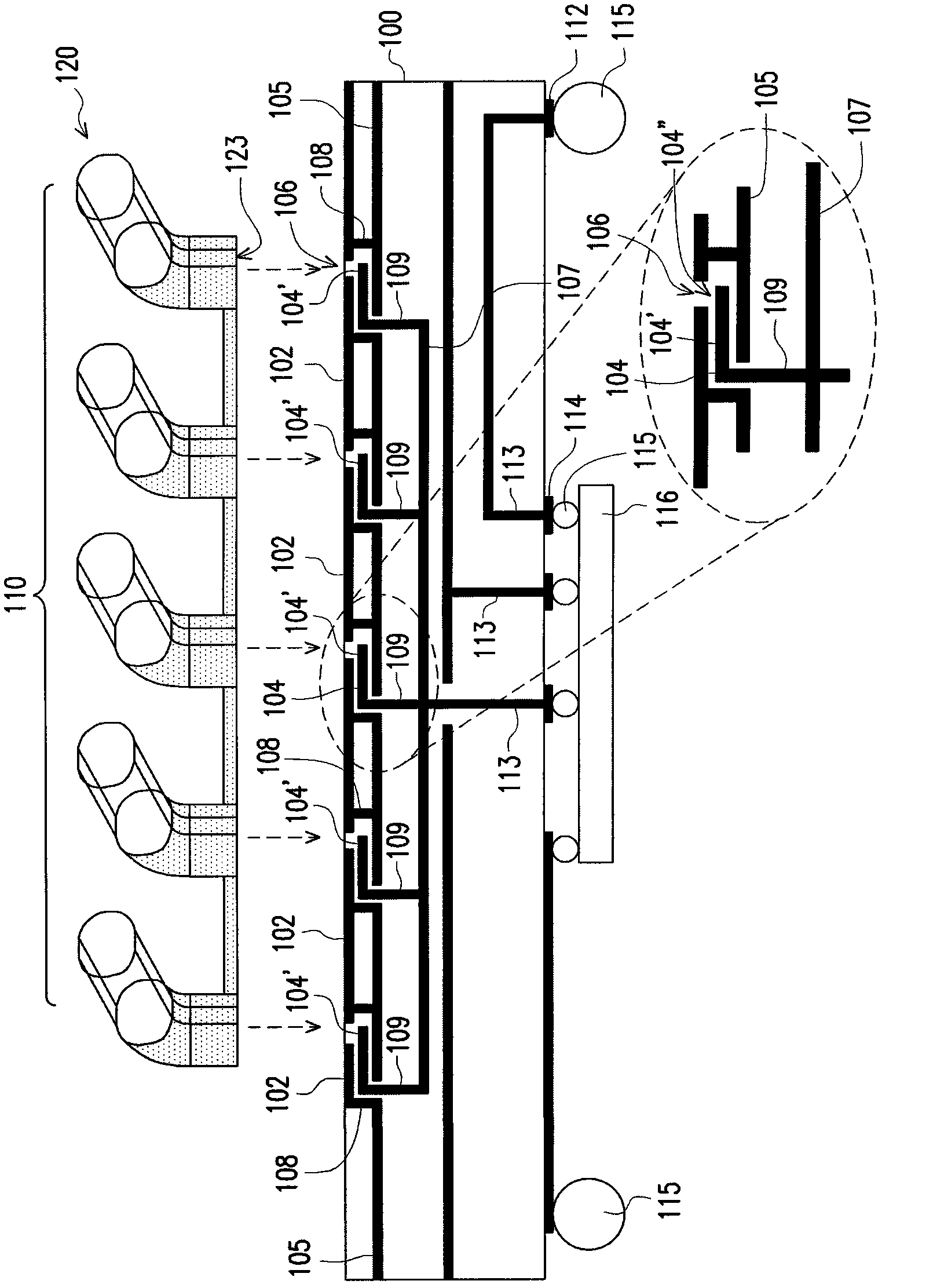
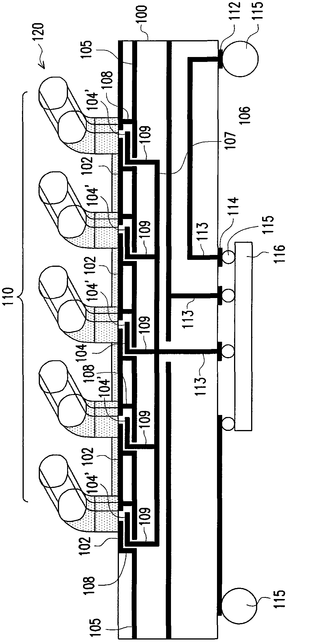
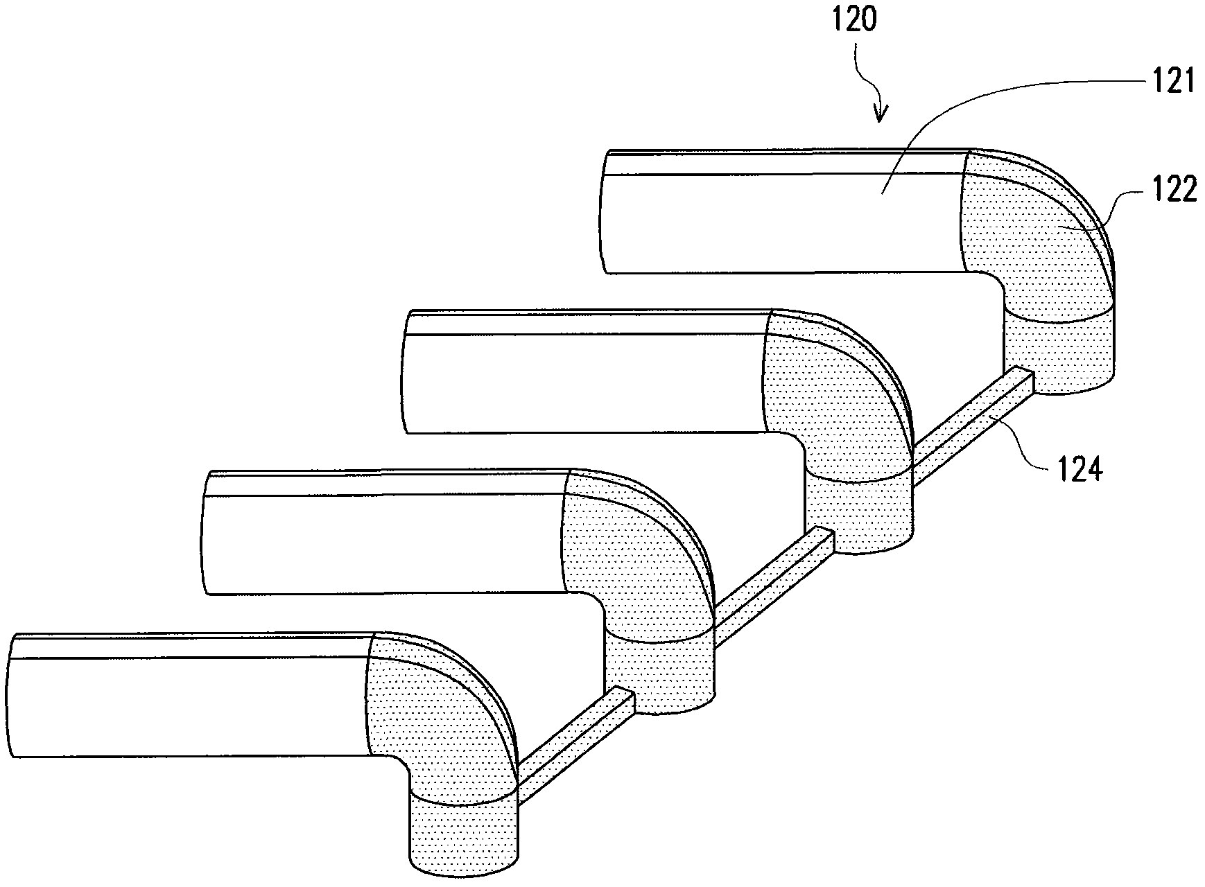
[0069] Below in conjunction with accompanying drawing, structural principle and working principle of the present invention are specifically described:

[0070] The antenna provided by the present invention adopts a dielectric antenna (Dielectric Antenna), can be packaged with a chip, and is applicable to, for example, a millimeter-wave high-gain antenna module and the like. In addition, it can also be combined with low-temperature co-fired ceramic technology to make a multi-layer circuit carrier (carrier).

[0071] The invention provides the structure of the dielectric antenna and the antenna module formed by it, which can be easily assembled to meet the precision requirements. In addition, it also allows the combination of various radiation angles, so as to achieve easier operation efficiency in response to the position changes of various devices in the use environment. .

[0072] The antenna module provided by the invention has simple structure, high unit density, can be in...


PUM


Abstract

A dielectric antenna and an antenna module are provided. The dielectric antenna includes at least one dielectric unit. Each dielectric unit is separated into a first region and a second region, and the second region could have a bending portion. A conductor covers a surface of the second region of the dielectric unit to form a waveguide structure. The waveguide structure has a first endpoint connected to the first region and a second endpoint serving as a signal feeding terminal for feeding or receiving signals. The dielectric antenna can be packaged with a chip and thus is suitable for millimeter-wave high gain antenna modules.

Description

technical field [0001] The invention relates to an antenna technology, in particular to a dielectric antenna and an antenna module. Background technique [0002] Antennas are essential elements in wireless communications. With the increase in the demand for data transmission in wireless communication, the millimeter wave frequency band has a large available bandwidth, for example, the 60GHz frequency band can have a bandwidth of 7GHz, allowing various applications in communication. On the other hand, due to the advancement of semiconductor technology, the RF front-end single chip can be realized. Compared with the previous modules made of discrete components, the integrated chip can reduce the size of the module, reduce the complexity of assembly, reduce the cost, and provide the important function of beam switching. [0003] Taking millimeter wave as an example, due to the large transmission loss of 60GHz millimeter wave in the atmosphere, a large effective isotropically ...

Claims


Application Information

Patent Timeline
Patent Type & Authority Applications(China)
IPC IPC(8): H01Q1/38H01Q1/22
CPCH01L2223/6677H01L2224/16227H01L2924/15192H01L2924/15321H01Q13/24H01Q21/0006H01Q21/08H01Q21/205
Inventor 林弘萱浦大钧吴俊熠
Owner IND TECH RES INST
Why Eureka
Try Eureka