
Ground zero-gravity test device for small-space one-dimension extension mechanism

A technology of stretching mechanism and test device, which is applied in the field of aerospace, can solve the problems of complex device composition, large deployment resistance, and large space occupation, and achieve the effect of simple and easy design, strong adaptability, and convenient movement

Inactive Publication Date: 2013-07-10
BEIHANG UNIV
View PDF5 Cites 37 Cited by
  • Summary
  • Abstract
  • Description
  • Claims
  • Application Information

AI Technical Summary

Problems solved by technology

Since the unfolding action is carried out in water, the water resistance is much greater than that of the air, so that the unfolding resistance is very large, and the simulated vacuum zero-gravity state has a large distortion. At the same time, water may pollute the test equipment. This method is rarely used.
[0021] Although the above four methods can achieve a certain degree of zero-gravity environment, they all have certain deficiencies, especially for spatial one-dimensional stretching mechanisms, which are difficult to make up for.
The composition of the air flotation platform device is relatively complex, the control is difficult, and it is impossible to carry out joint test verification under vacuum conditions; the two-dimensional suspension equipment sling [9] is difficult to accurately control the gravity compensation of the stretching mechanism, and the equipment is complex and occupies a large space , the cost of testing the whole equipment in a vacuum environment facility is relatively high; the air resistance and occupied space of the balloon suspension method are large, which is difficult to realize in a vacuum environment; the water suspension method has a large resistance, pollutes the test equipment and is difficult to operate Realized in a vacuum

Method used


Image

  • Ground zero-gravity test device for small-space one-dimension extension mechanism
  • Ground zero-gravity test device for small-space one-dimension extension mechanism

Examples


Embodiment Construction

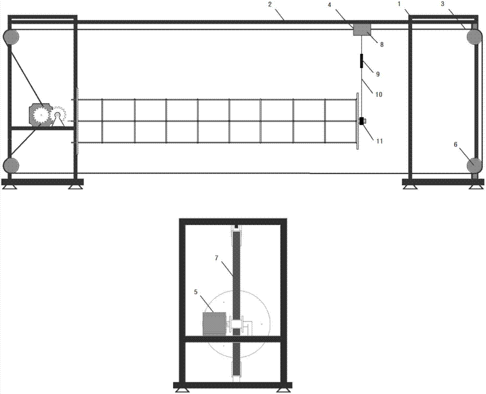
[0035] In the example, the coil-type spatial expansion arm of the cable expansion type is used as the expansion test mechanism for illustration.

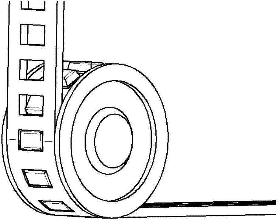
[0036] The ground zero-gravity test device of the space one-dimensional extension mechanism of the present invention includes a support system [1], a guide rail system [2], a drive and synchronization system [3], and a suspension system [4], based on an optical platform and a frame-type support structure The structure uses the square hole synchronous belt [7] and the bearing pulley [6] with square teeth to mesh for synchronous transmission. The motor [5] drives the cable to expand the coiled space extension arm, and passes through the slip ring [10] at the top of the extension arm. ], sling [9] connect slide block [8] and carry out one-dimensional expansion on the guide rail.

[0037] The accompanying drawing is a schematic structural view of a preferred embodiment of the ground zero-gravity test device for a space one-dimensional e...


PUM


Abstract

The invention relates to a ground zero-gravity test device for a small-space one-dimension extension mechanism for a spacecraft to overcome the defects of various test devices in the prior art and to solve the problem that the small-space one-dimension extension mechanism simulates the zero-gravity state of in-orbit operation in the ground gravity environment and to further solve the problem about compatibility of the small-space one-dimension extension mechanism with the comprehensive operation of the vacuum test and the thermal test. The ground zero-gravity test device adopts the principle of square teeth meshing and combines the real-time synchronism of a synchronous belt to vertically hang a tested mechanism. The ground zero-gravity test device is simple and feasible in design, small in size and light in weight, convenient to move, and strong in adaptability to the environment, can effectively operate in a vacuum or thermal environment condition, and can be used for testing the expanding characteristic of one-dimension extension mechanisms like a coiled extension arm and a thin-wall tubular extension arm.

Description

technical field [0001] This patent relates to a ground zero-gravity test device for a small space one-dimensional stretching mechanism, which is applied to a zero-gravity environment simulation test of a space one-dimensional stretching mechanism, and belongs to the field of aerospace technology. Background technique [0002] With the increasingly complex functions of spacecraft and the further application of large payloads, space deployment mechanisms, especially one-dimensional extension mechanisms, have gradually received more attention and development due to their light weight and good ductility. The small space one-dimensional stretching mechanism is the earliest, the deepest, the most systematic, the most mature technology, and the most widely used. Small-scale space one-dimensional extension mechanisms are mainly one-dimensional linear systems, which are slender tubes, rods or frames, which can be used for large-scale space extendable antennas, solar cell arrays, sola...

Claims


Application Information

Patent Timeline
Patent Type & Authority Applications(China)
IPC IPC(8): B64G7/00G01M99/00
Inventor 王新升黄海马海波戴勇超管帅
Owner BEIHANG UNIV
Learn More