Production method of high pressure rubber tube wire

A production method and technology of high-pressure rubber hose, which is applied in the field of pressure hose steel wire and its production, and can solve the problems of uneven heating of steel wire, increased wire breakage rate, and poor cleaning performance.

Inactive Publication Date: 2013-07-17
JIANGSU SHENGDA TECH
View PDF1 Cites 6 Cited by
  • Summary
  • Abstract
  • Description
  • Claims
  • Application Information

AI Technical Summary

Problems solved by technology

[0003] When the traditional process is used to produce rubber hose steel wire, the steel wire is generally directly heated for austenitization. Since there is residual borax soap powder on the surface of the steel wire due to drawing, this will cause the steel wire to not receive the heat from radiation evenly in the furnace, further resulting in poor cleaning performance
In addition, due to the residual zinc oxide on the coating surface of the rubber hose steel wire after galvanizing, the broken wire rate will increase during the subsequent drawing process

Method used


Image

  • Production method of high pressure rubber tube wire
  • Production method of high pressure rubber tube wire
  • Production method of high pressure rubber tube wire

Examples


Embodiment 1

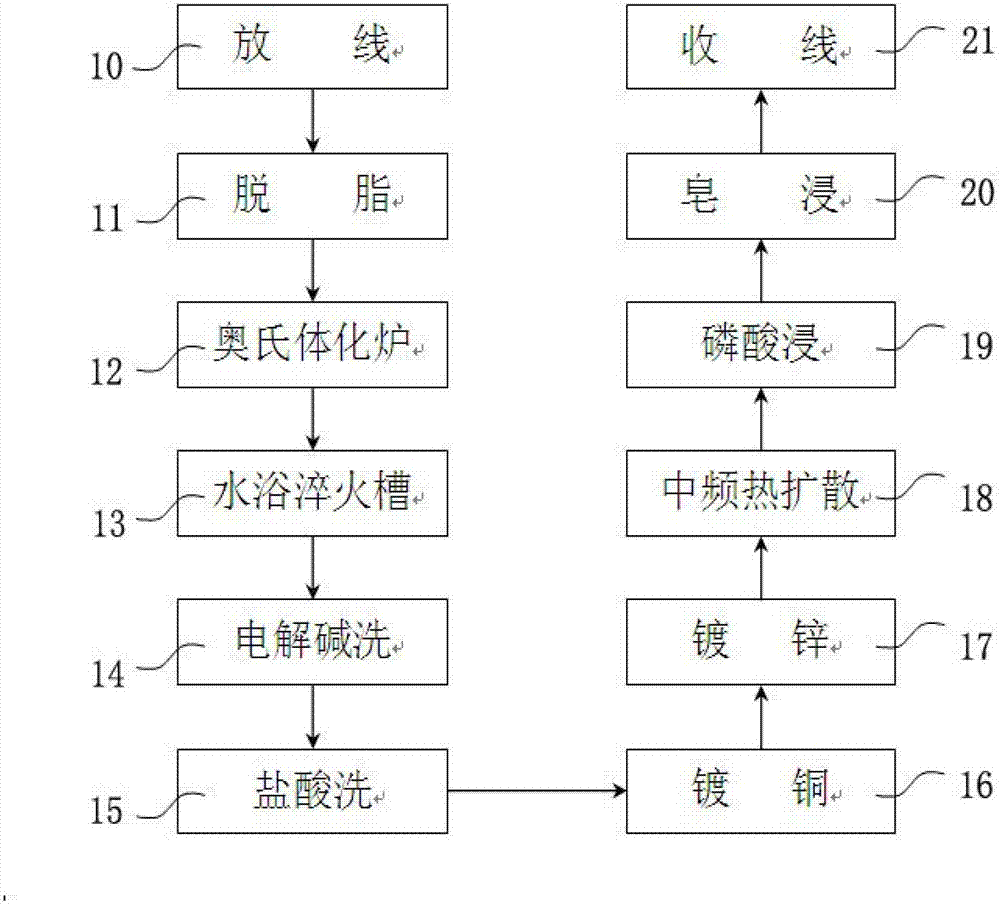
[0037] Such as figure 1 As shown, the present invention provides a kind of high-pressure rubber hose steel wire and production method thereof, comprising the following steps:

[0038] (10) The steel wire of the rubber hose after intermediate drawing is paid off through the pay-off device, and the tension is constant during the pay-off process, so as to avoid the fluctuation of the tension and the large dispersion of the performance of the strip.

[0039] (11) The steel wire of the rubber hose enters the degreasing tank for degreasing, and the borax soap powder remaining on the surface is washed away, so that the steel wire can evenly receive the heat from radiation in the furnace. The degreasing medium is soap powder, and the set temperature of the degreasing tank is ≥85°C. If the temperature is too low, the flow of the degreasing liquid will be affected. Moreover, the coated soap solution can control the heating rate of the steel wire in the furnace, control the oxidation pr...

Embodiment 2

[0062] On the basis of the above examples, if figure 1 Shown, a kind of high-pressure hose steel wire production method, wherein, comprises the following steps:

[0063] Step 10: The drawn rubber hose steel wire passes through the wire-releasing device for wire-releasing;

[0064] Step 11: enter the degreasing tank for degreasing;

[0065]Step 12: entering an austenitizing furnace for structural transformation;

[0066] Step 13: After the internal structure of the steel wire is transformed into austenite, it enters the water bath quenching tank;

[0067] Step 14: The steel wire enters the electrolytic alkaline washing tank;

[0068] Step 15: Hose steel wire enters hydrochloric acid washing;

[0069] Step 16: Enter the copper electroplating process after being washed with high-pressure water;

[0070] Step 17: the steel wire enters the galvanizing process;

[0071] Step 18: After the steel wire is preheated and cleaned with high-temperature hot water, the surface of the s...


PUM


Abstract

The invention relates to a production method of a high pressure rubber tube wire. The production method comprises the following steps of: S10, paying off a pulled rubber tube wire through a paying off device; S11, degreasing; S12, entering into an austenitizing furnace; S13, entering a water bath quenching tank; S14, entering an electrolytic alkaline bath by the steel wire; S15, entering a hydrochloric acid bath by the rubber tube wire; S16, washing at high pressure and entering into an electrocoppering step; S17, entering a galvanizing step by the steel wire; S18, preheating and washing high temperature hot water by the steel wire to enter into middle frequency thermal diffusion; S19, entering into a phosphoric acid bath by thermally diffused rubber tube wire; S20, soaping and drying the steel wire; and S21, entering to a winding device after water washing. With the technical scheme, the problem of poor universality of the steel wire can be improved, and the breakage rate in the pulling process can be effectively reduced.

Description

technical field [0001] The invention relates to a production method of a high-pressure rubber hose steel wire, which is used as a reinforcing material for a hydraulic rubber hose made of carbon steel wire rods, in particular to a pressure rubber hose steel wire and a production method thereof. Background technique [0002] With the continuous development of mining engineering machinery in my country and the world, the requirements for high-strength hydraulic hoses that transmit hydraulic power are further improved. service life. [0003] When the traditional process is used to produce rubber hose steel wire, the steel wire is generally directly heated for austenitization. Since there is residual borax soap powder on the surface of the steel wire due to drawing, this will cause the steel wire to not receive the heat from radiation evenly in the furnace, further Resulting in poor cleaning performance. In addition, due to the residual zinc oxide on the coating surface of the r...

Claims


Application Information

Patent Timeline
Patent Type & Authority Applications(China)
IPC IPC(8): C23F17/00
Inventor 陆海
Owner JIANGSU SHENGDA TECH
Why Eureka
Try Eureka