Industrial computed tomography (CT) image reconstruction centralized positioning method based on point spread function

A point spread function, CT image technology, applied in image analysis, image data processing, instruments and other directions, can solve the problems of low positioning accuracy, large noise impact, low accuracy, etc., to achieve convenient operation, high practical value, simple production. Effect

Active Publication Date: 2013-07-24
CHONGQING UNIV
View PDF2 Cites 13 Cited by
  • Summary
  • Abstract
  • Description
  • Claims
  • Application Information

AI Technical Summary

Problems solved by technology

[0003] Fu Jian and others solved the position offset of each projection value through the relationship between the offset of the ray source and the offset of any point on the workpiece projected on the detector, and moved the ray source multiple times, and iteratively reconstructed the CT image. Determine the image reconstruction center, the positioning accuracy of this method is not high, and the use of image signal-to-noise ratio to judge the clarity of image reconstruction cannot achieve the expected effect
[0004] According to the principle of symmetry of the projected sinogram about the center of rotation, Zhang Wei et al. first segment the projected sinusoidal image, and then find the projected centroid of the object projected in all directions, and finally weight all centroid positions to find the mean value. The advantages of this method are: Reduce the influence of noise, but when the density of the scanned object is low, the projection image segmentation is inaccurate, resulting in low positioning accuracy
[0005] Li Baolei and others used the symmetric relationship between the projected sinogram and the rotation center under the third-generation CT scan and 360° rotation mode, that is, the relationship between the

Method used


Image

  • Industrial computed tomography (CT) image reconstruction centralized positioning method based on point spread function
  • Industrial computed tomography (CT) image reconstruction centralized positioning method based on point spread function
  • Industrial computed tomography (CT) image reconstruction centralized positioning method based on point spread function

Examples


Embodiment Construction

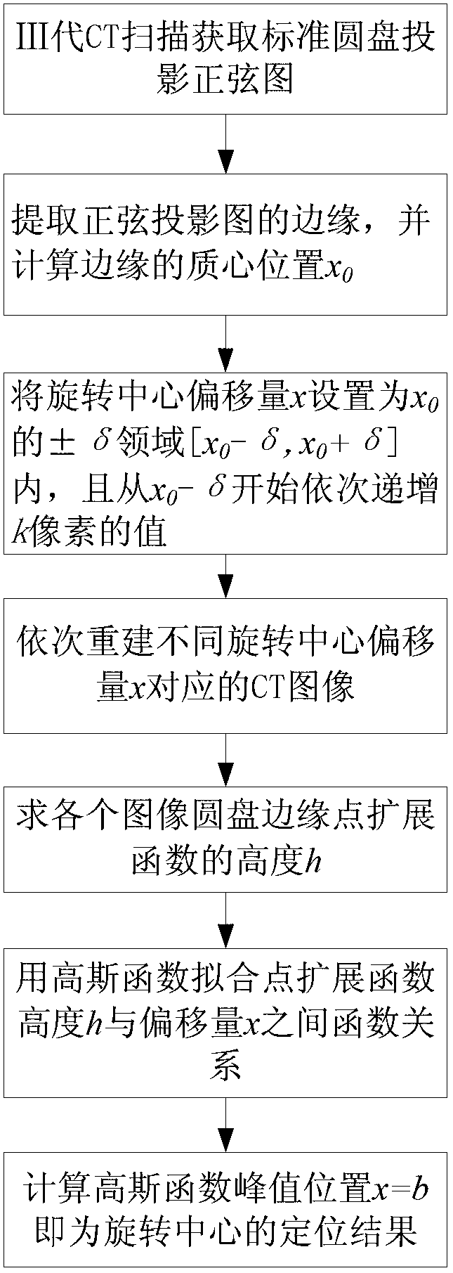
[0053] The present invention will be further described below in conjunction with drawings and embodiments.

[0054] Image reconstruction of the third-generation CT scan is based on the assumption that when the fan-shaped beam is projected in rotation, the center ray passes through the center of rotation, or the position of the rotation center in the fan-shaped ray beam is known. The actual CT system must do this One point is very difficult, and it takes a lot of experiments to do it during the initial debugging of the equipment; and after the equipment has been used for a period of time, due to factors such as changes in the environment and load, this relative position will also shift, and it is laborious and time-consuming to find the correct position. The purpose of this method is to quickly, automatically and more accurately determine the relative position of the rotation center in the fan beam to determine the image reconstruction center. The essence is to obtain the offset...


PUM


Abstract

The invention discloses an industrial computed tomography (CT) image reconstruction centralized positioning method based on a point spread function, and relates to the field of CT scan image construction. The industrial CT image reconstruction centralized positioning method particularly includes the following steps: (1) obtaining the tomographic projection data of middle portion of a to-be-measured disc in the thickness direction, obtaining a projection sonogram; (2) calculating the marginal location x 0 of the center of mass; (3) letting that the offset x of the rotation center of the disc is be the range of from x 0 minus delta to x 0 plus delta, reconstructing the CT images corresponding each offset x by applying a filtered back projection reconstruction algorithm; and (4) determining the height h of the point spread function (PSF) of disc margin in each reconstructed CT image, fitting the function relationship of an image reconstruction center offset x and the height h of the PSF of disc margin, and calculating the image reconstruction center offset.

Description

technical field [0001] The invention relates to the field of CT scan image construction, in particular to a method for center positioning of industrial CT image reconstruction. Background technique [0002] Image reconstruction of the third-generation CT scan is based on the assumption that when the fan-shaped beam is projected in rotation, the center ray passes through the center of rotation, or the position of the rotation center in the fan-shaped ray beam is known. The actual CT system must do this One point is very difficult. In the initial debugging stage of the equipment, it takes a tedious trial and error process to meet the accuracy requirements; and when the equipment is used for a period of time, due to factors such as environment and load changes, the position of the rotation center will drift, and it will be laborious and time-consuming to find the correct position. . There are many solutions to this problem, mainly iterative method, sinogram center of gravity m...

Claims


Application Information

Patent Timeline
IPC IPC(8): G06T7/60
Inventor 王珏刘明进蔡玉芳
Owner CHONGQING UNIV
Why Eureka
Try Eureka