Square wave detector for wireless wake-up circuit

A wake-up circuit and detector technology, applied in the field of radio frequency electronics, can solve the problems of high probability of false wake-up, high cost of printed circuit board-level design, and reduced wake-up time.

Active Publication Date: 2013-07-31
杭州中科微电子有限公司
View PDF9 Cites 12 Cited by
  • Summary
  • Abstract
  • Description
  • Claims
  • Application Information

AI Technical Summary

Problems solved by technology

[0008] The purpose of the present invention is to distinguish the NkHz (such as 14K) square wave output by the wake-up receiver in RFID in order to overcome the problems of high design cost at the printed circuit board level, complex peripheral circuit structure, and high probability of false wake-up in the prior art. Processing, improve the wake-up probability of the correct signal, reduce the probability of false wake-up caused by the wrong signal, and reduce the wake-up time

Method used


Image

  • Square wave detector for wireless wake-up circuit
  • Square wave detector for wireless wake-up circuit
  • Square wave detector for wireless wake-up circuit

Examples


no. 1 example

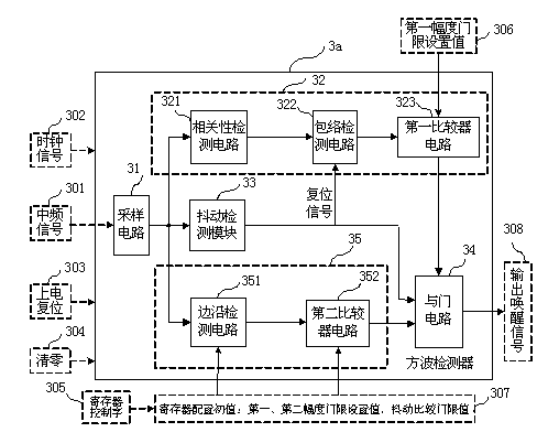
[0077] Figure 3a Provide the structural block diagram of the 14kHz square wave detector that N is 14 in the first embodiment of the present invention applied in the ETC system, as Figure 3a As shown: the square wave detector 3 a includes a sampling circuit 31 , a correlation detection module 32 , a jitter detection module 33 , a frequency detection module 35 and an AND gate circuit 34 . The correlation detection module 32 includes a correlation detection circuit 321 , an envelope detection circuit 322 and a first comparator circuit 323 sequentially connected in series. The frequency detection module 35 includes an edge detection circuit 351 and a second comparator circuit 352 . The output end of the jitter detection module 33 and the output end of the second comparator circuit 352 of the frequency detection module 35 are respectively connected to an input end of the AND gate circuit, and the output end of the first comparator circuit 323 of the correlation detection module ...

no. 2 example

[0079] Figure 3b It is a structural block diagram of a 14kHz square wave detector with N being 14, which is applied in the ETC system according to the second embodiment of the present invention. like Figure 3b As shown: the square wave detector includes a sampling circuit 31 , a correlation detection module 32 , a jitter and frequency detection module 36 combined by a jitter detection circuit and a frequency detection circuit, and an AND circuit 34 . The correlation detection module 32 includes a correlation detection circuit 321 , an envelope detection circuit 322 and a first comparator circuit 323 sequentially connected in series. The jitter detection module and the frequency detection module are combined into a jitter and frequency detection module 36 , which includes a jitter detection circuit 361 , an edge detection circuit 362 , and a second comparator circuit 363 . The output ends of the jitter detection circuit 361 and the edge detection circuit 362 are respectivel...

no. 3 example

[0081] The schematic block diagram of the circuit composition of the correlation detection module is as follows: Figure 4 shown. The correlation detection module is composed of cross-correlation operation mixers 411 and 412 , a digital oscillator 413 , two cross-correlation integration and accumulation circuits 42 and 43 , an envelope detection circuit 322 and a first comparator circuit 323 . The integration and accumulation circuit 42 includes a first integrator circuit 421 and a first accumulator circuit 422 connected in series; the integration and accumulation circuit 43 includes a second integrator circuit 431 and a second accumulator circuit 432 connected in series; the second integrator The output of circuit 431 is applied to the input of first integrator circuit 421 . The circuit connection of the correlation detection module path is as follows: the output terminal of the digital oscillator 413 is connected with the local oscillator signal input terminals of the two-w...


PUM


Abstract

The invention provides a square wave detector for a wireless wake-up circuit. The frequency of the square wave detector can be configured within the range of 10-200 kHz. The square wave detector comprises a signal acquisition circuit and a square wave detection circuit, wherein the square wave detection circuit comprises a jitter detection module path, a frequency detection module path, a relevant detection module path and an AND circuit which are used for respectively detecting the duty factor, the frequency and the relevance of an input sampling signal; and when outputs of the three detection module paths are high levels respectively, the output of the AND circuit is also high level and the square wave detection circuit outputs a wake-up signal. By detecting the jitter, the frequency and the relevance of the input sampling signal, the accurate judgment and clutter reduction are realized, the mistaken wake-up probability is effectively reduced, the wake-up probability is increased and the wake-up time is remarkably shortened, thereby increasing the work efficiency of a wake-up receiver and reducing the power consumption of the system. The square wave detector provided by the invention is suitable for wake-up receiving circuits of an RFID (Radio Frequency Identification) system and an ETC (Electronic Toll Collection) system.

Description

technical field [0001] The invention belongs to the technical field of radio frequency electronics, and relates to a wake-up receiving circuit of a radio frequency identification RFID system, in particular to a square wave detector for a wireless wake-up circuit, which is suitable for an active RFID system and an electronic toll collection ETC system, and effectively improves the Wake up the efficiency of the receiver. Background technique [0002] In recent years, radio frequency identification (RFID) technology has developed rapidly, and the RFID system is mainly composed of a radio frequency identification reader (reader) and a radio frequency tag (tag). RFID systems are divided into active RFID systems and passive RFID systems according to whether the radio frequency tag has a built-in power supply. The tags of the active RFID system have built-in power supply and have the advantages of high reliability and long-distance communication, so they have been favored in recen...

Claims


Application Information

Patent Timeline
Patent Type & Authority Applications(China)
IPC IPC(8): G01R29/02G01R23/06G01R25/00
Inventor 何文涛葛亮甘业兵钱敏马成炎
Owner 杭州中科微电子有限公司
Why Eureka
Try Eureka