Beam array phase control system and method based on multiphase perturbation

A phase control and control system technology, applied to lasers, laser components, electrical components, etc., can solve problems such as cost and system control speed drop, avoid iterative process, improve control speed and control bandwidth, and control circuit structure is simple Effect

Inactive Publication Date: 2013-07-31
INST OF APPLIED PHYSICS & COMPUTATIONAL MATHEMATICS
View PDF2 Cites 12 Cited by
  • Summary
  • Abstract
  • Description
  • Claims
  • Application Information

AI Technical Summary

Problems solved by technology

The electronic frequency standard method modulates each sub-beam with a radio frequency sinusoidal small signal, attaches a mark to each signal, and separates the phase difference information from the output current of the detector through electrical correlation detection; in addition, in order to ensure the correct separation of the phase information, The time of relevant detection τ It needs to be as long as possible, but the system control speed is inversely proportional to τ , taking into account the control speed and detection accuracy in practice, τ Generally, 10 times the RF sine modulation cycle is taken. Since the RF sine modulation cycle generally requires more than 50 times the clock cycle, the correlation detection will take 500 times the clock cycle; when the phases of each beam are relatively consistent, the feedback control signal of the electronic frequency standard method is approximately proportional in the phase difference value, but when the phase difference is close to π When the amount of feedback is small, multiple iterations are required to achieve convergence, resulting in a decrease in system control speed

Method used


Image

  • Beam array phase control system and method based on multiphase perturbation
  • Beam array phase control system and method based on multiphase perturbation
  • Beam array phase control system and method based on multiphase perturbation

Examples


Embodiment Construction

[0019] The following examples are used to illustrate the present invention, but not to limit the present invention. Those skilled in the art can also make various changes and modifications without departing from the spirit and scope of the present invention. Therefore, equivalent technical Schemes are also within the scope of the present invention.

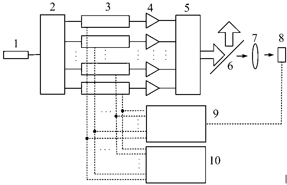
[0020] figure 1 It is a structural schematic diagram of the beam array phase control system of the multi-phase perturbation of the present invention, such as figure 1 As shown, the beam array phase control system of multi-phase perturbation of the present invention includes a laser source 1, a beam splitter 2, a phase controller 3, an optical amplifier 4, an optical calibration transmitter 5, a beam splitter 6, a far-field imaging device 7, and a detection device 8, phase control algorithm module 9, multi-phase disturbance generation module 10. Laser source 1 is a 1064nm ytterbium-doped fiber laser, and the output light passes...


PUM


Abstract

The invention provides a beam array phase control system and a method based on multiphase perturbation. Emergent laser of a laser source in the control system is input to a beam splitter; multichannel laser output by the beam splitter is input to corresponding phase controllers respectively; the phase controllers are sequentially connected with optical amplifiers and an optical collimation emitter; the optical collimation emitter is sequentially connected with an optical splitter and a far field image device; the far field image device inputs the laser into a detector; an electrical signal output by the detector is input into a phase control algorithm module; the phase control algorithm module outputs a multichannel electrical control signal to the corresponding phase controllers; and a multiphase perturbation generation module outputs a multichannel electrical modulating signal to the corresponding phase controllers. With the adoption of the system and the method, the performance of a coherent combination system can be improved, and large-scale beam combining capacity can be achieved.

Description

technical field [0001] The invention relates to the field of coherent combination and beam control, in particular to a beam array phase control system and method based on multi-phase perturbation. Background technique [0002] Due to its advantages in thermal management and beam control, the coherent combination of multiple lasers has become one of the feasible ways to break through the limitations of factors such as thermal effects and laser medium characteristics, and obtain laser output with higher average power and high beam quality. The realization of coherent combination requires the use of phase control technology to lock the phases of each laser beam to achieve an approximately consistent state. Due to the influence of various sources of phase noise, the phase of each beam in a practical system will change dynamically. In order to ensure the effective locking of the system phase, the phase control speed is an important index to evaluate the system performance. At p...

Claims


Application Information

Patent Timeline
Patent Type & Authority Applications(China)
IPC IPC(8): H01S3/10
Inventor 唐选王小军黄智蒙
Owner INST OF APPLIED PHYSICS & COMPUTATIONAL MATHEMATICS
Why Eureka
Try Eureka