Impurity removal agitator tank

A mixing tank and mixing shaft technology, applied in the field of mixing tanks with impurity removal function, can solve the problems of affecting the production process, time-consuming and laborious, increasing the risk factor, etc. Effect

Inactive Publication Date: 2013-08-07
TIANJIN FUYUAN BUILDING MATERIALS CO LTD
View PDF8 Cites 7 Cited by
  • Summary
  • Abstract
  • Description
  • Claims
  • Application Information

AI Technical Summary

Problems solved by technology

The above-mentioned operation method is time-consuming and laborious, seriously affects the production process, and also increases the risk factor in the production process

Method used


Image

  • Impurity removal agitator tank

Examples


Embodiment Construction

[0011] In order to further understand the content of the invention, characteristics and effects of the present invention, the following examples are described in detail as follows:

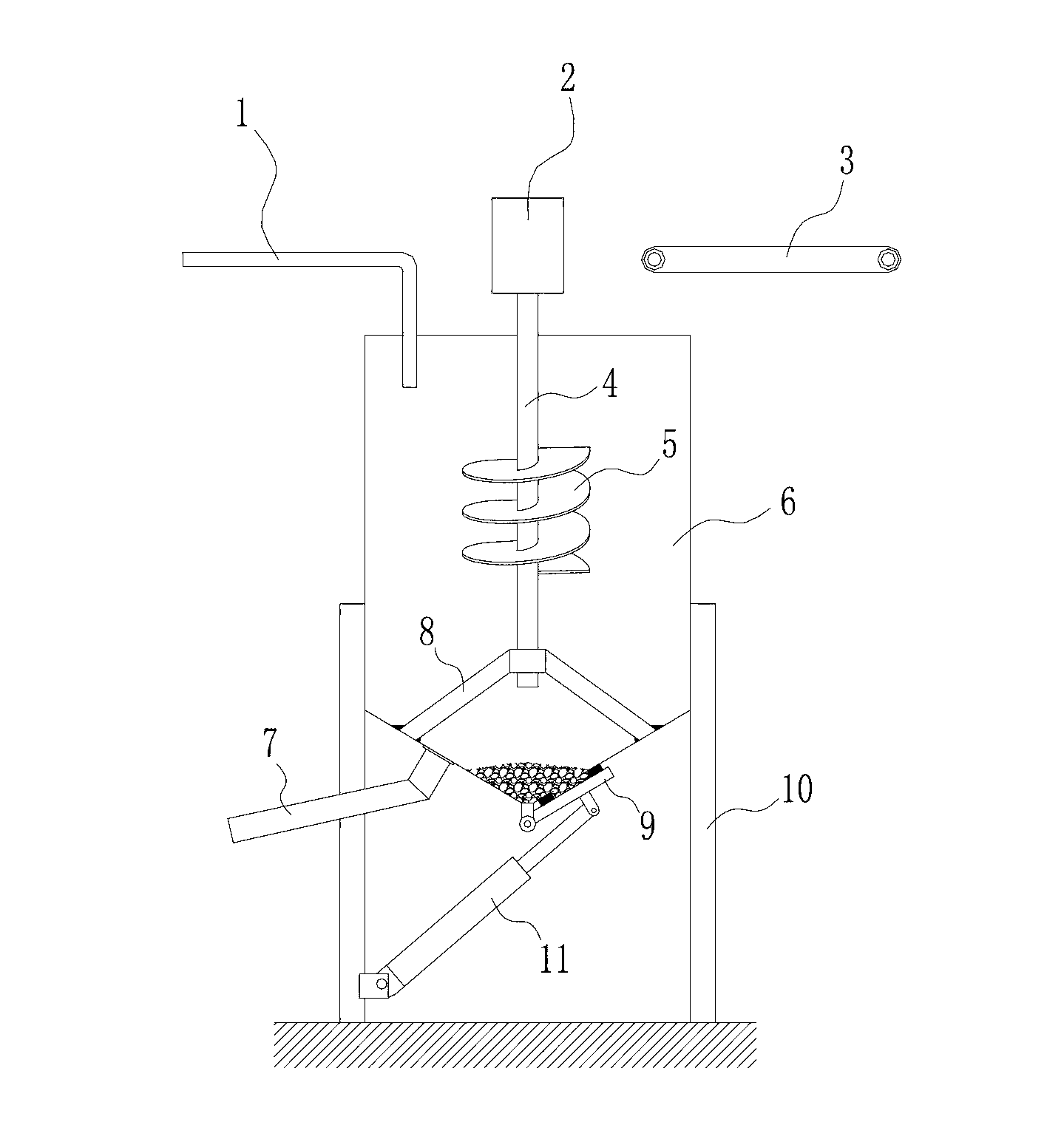
[0012] See figure 1 , the present invention comprises a tank body 6, a driver 2, a stirring shaft 4 connected to the driving machine 2, and a stirring blade 5 positioned on the stirring shaft 4, and a shaft sleeve is sheathed at the bottom of the stirring shaft 4, and the shaft A plurality of support bodies 8 are provided between the sleeve and the inner wall of the tank body 6 to realize stable support for the stirring shaft 4 and make it rotate smoothly. A water inlet pipe 1 is arranged above the tank body 6 for adding water, and a conveyor belt 3 is arranged for conveying raw materials such as fly ash.

[0013] The tank body 6 is supported by a plurality of uprights 10, and its bottom is in an inverted cone shape. The inverted cone-shaped structure facilitates the concentrated precipitation o...


PUM


Abstract

The invention belongs to the technical field of agitation equipment, and particularly relates to an agitator tank with an impurity removal function. The agitator tank comprises a tank body, a driving machine, an agitating shaft connected with the driving machine and an agitating blade positioned on the agitating shaft, wherein a shaft sleeve is further sleeved at the bottom end of the agitating shaft; a plurality of supporting bodies are arranged between the shaft sleeve and the inner wall of the tank body; the tank body is supported by a plurality of upright posts and the bottom of the tank body is inverted-cone-shaped; an impurity outlet is arranged on the side wall of the inverted-cone-shaped bottom; the agitator tank further comprises a buckle cover buckled on the impurity outlet, wherein the edge of the buckle cover is hinged with the bottom of the tank body, and a connecting lug plate is further arranged on the buckle cover; the agitator tank further comprises a hydraulic cylinder, wherein the end of a piston rod of the hydraulic cylinder is hinged with the connecting lug plate; and a discharging pipeline is further arranged at the bottom of the tank body, and the height of a connecting part of the discharging pipeline and the tank body is larger than that of the impurity outlet. According to the impurity removal agitator tank disclosed by the invention, the bottom of the tank body is arranged to be inverted-cone-shaped and the impurity outlet and the buckle cover are arranged, so that large grained impurity in size can be precipitated and merged and is convenient to take out.

Description

technical field [0001] The invention belongs to the technical field of stirring devices, in particular to a stirring tank with the function of removing impurities. Background technique [0002] In the field of unburned brick production, a stirring tank is used to achieve the mixing and stirring of the slurry. Unburned bricks have a wide range of sources of raw materials. Fly ash, slag, stone powder, coal gangue, etc. can be used as raw materials for production. After batching, these materials can form slurry in the mixing tank, and then enter the mold It is molded in the frame, and then cut to get the finished unfired brick. In the existing production, the stirring of the slurry is generally carried out through an ordinary stirring tank. Such a stirring tank usually includes a cylindrical tank body, a driving machine, a stirring shaft and a stirring blade. During the whole stirring process, the large pieces mixed in the raw materials Stones and other sundries gradually set...

Claims


Application Information

Patent Timeline
Patent Type & Authority Applications(China)
IPC IPC(8): B28C3/00B01F7/24B01F3/12B01F15/00B01F15/02
Inventor 曹彦岭
Owner TIANJIN FUYUAN BUILDING MATERIALS CO LTD
Why Eureka
Try Eureka