
Quick batch test device for light, color and electricity performance of LED

A light-emitting diode and batch testing technology, which is applied in testing optical performance and lamp testing, can solve the problems of unsuitable light-emitting diode LED rapid testing, long time consumption, and low efficiency of optical performance testing, achieving high integration and low efficiency , the effect of improving efficiency

Inactive Publication Date: 2013-08-14
SHANGHAI UNIV
View PDF7 Cites 14 Cited by
  • Summary
  • Abstract
  • Description
  • Claims
  • Application Information

AI Technical Summary

Problems solved by technology

The existing light-emitting diode LED photochromic and electrical performance testing device is not suitable for rapid testing of light-emitting diode LED photochromic and electrical performance in large quantities. Traditional power semiconductor LED optical performance testing is inefficient and time-consuming

Method used


Image

  • Quick batch test device for light, color and electricity performance of LED
  • Quick batch test device for light, color and electricity performance of LED
  • Quick batch test device for light, color and electricity performance of LED

Examples


Embodiment 1

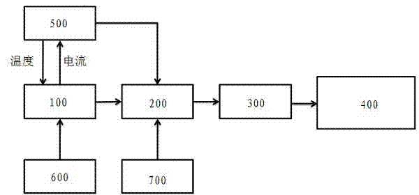
[0021] In this example, see figure 1 , a light-emitting diode LED light, color and electricity performance rapid batch testing device, including a control circuit board 100, an integrating sphere 300, a PC 400, a heating module 500, a constant voltage source module 600 and a constant current source module 700, a constant voltage source module 600 A 350mA constant current source is used to power the drive control circuit board 100, the semiconductor LED device 200 to be tested is powered by the constant current source module 700, the integrating sphere 300 is used to test the optical performance of the semiconductor LED device 200 to be tested, and the test results are transmitted to the PC 400, the integrating sphere 300 adopts the HAAS-2000 integrating sphere of Yuanfang Optoelectronics, the PC 400 processes the data transmitted by the integrating sphere 300 and displays the results, the heating module 500 is connected to the control circuit board 100 for signals, and batches ...

Embodiment 2

[0025] This embodiment is basically the same as Embodiment 1, especially in that:

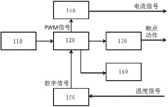
[0026] In this example, see image 3 , the heating drive module 140 is built based on an operational amplifier circuit, which is composed of an integral module 142, a voltage follower module 144, a second-order filter module 146 and a comparison voltage output module 148 in series to form a drive circuit, and the integral module 142 is used to convert the pulse width modulation signal into Sawtooth signal, the voltage following module 144 realizes voltage buffering, the second-order filter module 146 filters out the burrs of the sawtooth signal, and finally the comparison voltage output module 148 compares the sawtooth signal with the reference voltage and outputs the corresponding control signal, and sends the control signal It is added to the gate level of a field effect transistor (MOSFET), so as to realize the adjustment of the output current, and finally control the heating element of the ...

Embodiment 3

[0028] This embodiment is basically the same as the previous embodiment, and the special features are:

[0029] In this embodiment, the heating module 500 adopts a semiconductor heating and cooling chip, and can adopt a semiconductor heating and cooling chip TEC1-12706, which has high cooling efficiency and is easy to realize digital signal control.


PUM


Abstract

The invention discloses a quick batch test device for light, color and electricity performance of an LED. The device comprises a control circuit board, an integration ball, a PC, a heating module, a constant voltage source module and a constant current source module, wherein the control circuit board controls a semiconductor LED component to be turned on or off through a button, and at the same time, a temperature which is fed back is detected. Output current of the heating and driving module is adjusted in real time, and the constancy of the temperature of the heating module is maintained. According to the device, an embedded type control system is designed, a same test temperature is provided for each LED, and each LED is turned off or turned on separately, so that the test efficiency of the power semiconductor LED component is greatly improved. The test device has remarkable advantages in convenience, rapidity and accuracy of the measurement, and can test the optical performance of power semiconductor LEDs in batches rapidly, so that screening can be performed rapidly and conveniently.

Description

technical field [0001] The invention relates to a photoelectric performance testing device of a semiconductor electroluminescent device, in particular to a photoelectric performance testing device of a light-emitting diode (LED), which is applied in the technical field of testing the photochromic and electric performance of a large number of light-emitting diodes (LEDs). Background technique [0002] High-power LEDs will generate a lot of heat when they work, causing significant changes in the PN junction temperature of the LED chip, which will have an important impact on the performance of the LED, resulting in changes in forward voltage drop, color temperature changes, wavelength red shift, and low photoelectric conversion efficiency. etc., affecting its photometric, chromatic and electrical parameters. The thermal resistance of LED is an important parameter that determines the photoelectric characteristics and life of LED. Excessive thermal resistance will directly lead t...

Claims


Application Information

Patent Timeline
Patent Type & Authority Applications(China)
IPC IPC(8): G01R31/44G01M11/02
Inventor 张建华阙秀福刘臻
Owner SHANGHAI UNIV
Learn More