

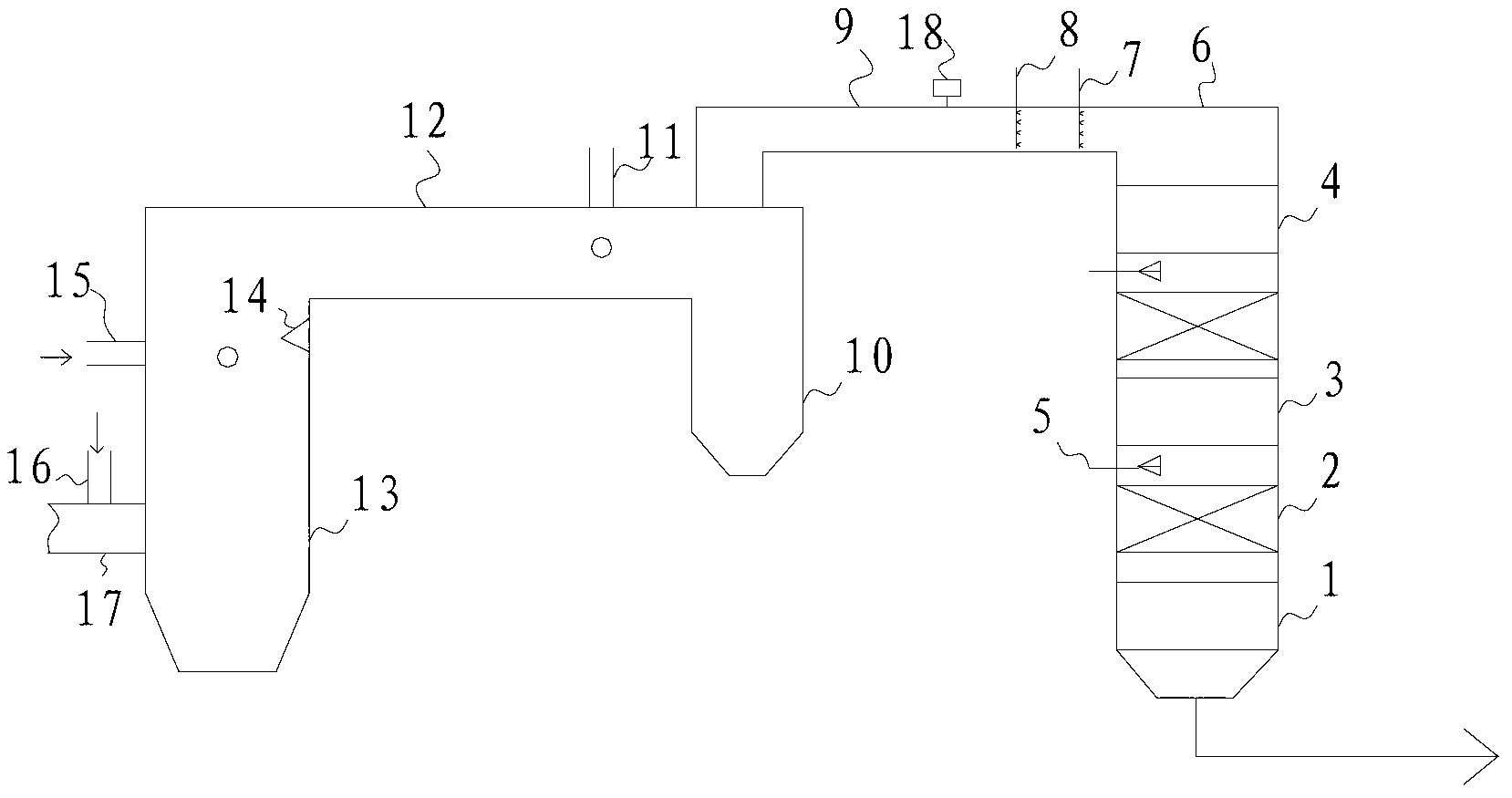
Device for removing NOX from smoke by combining ammonia agent spraying and built-in catalytic reaction
A catalytic reaction, built-in technology, applied in the direction of chemical instruments and methods, dispersed particle separation, separation methods, etc., can solve the problems of high operating costs, complex systems, large investment, etc., to avoid direct erosion, high NOX reduction rate, The effect of improving denitrification efficiency
- Summary
- Abstract
- Description
- Claims
- Application Information
AI Technical Summary
Problems solved by technology
Method used
Image

Examples
Embodiment 1
[0061] A circulating fluidized bed boiler NO X The initial emission concentration is 580mg / Nm 3 , sprayed with 20% ammonia water in the first three layers of three air ducts, flame angles, and cyclones. The NSR is 1.4, and its NO X The removal rate is 65%. The ammonia agent is not supplemented, and enters the 2-layer SCR catalyst for reaction. The catalyst adopts a module with a volume of 450*450*500mm and a corrugated type. The final denitrification efficiency reaches 87.5%, and no ammonia escape is detected at the tail.
Embodiment 2
[0063] A circulating fluidized bed boiler NO X The initial emission concentration is 580mg / Nm 3 , sprayed with 20% ammonia water in the first two layers of the flame angle and the cyclone, the NSR was 1.4, and its NO X The removal rate was 51.5%. The ammonia agent is not supplemented, and enters the 2-layer SCR catalyst for reaction. The catalyst adopts a module with a volume of 450*450*500mm and a corrugated type. The final denitrification efficiency reaches 84.5%, and no ammonia escape is detected at the tail.
Embodiment 3
[0065] A circulating fluidized bed boiler NOX The initial emission concentration is 580mg / Nm3, sprayed with 20% ammonia water in the first three layers of the three air ducts, the flame angle, and the cyclone, the NSR is 1.2, and its NO X The removal rate was 46.3%. The ammonia agent is not supplemented, and enters the 2-layer SCR catalyst for reaction. The catalyst adopts a module with a volume of 450*450*500mm and a corrugated type. The final denitrification efficiency reaches 72%, and no ammonia escape is detected at the tail.
PUM
 Abstract
Description
Claims
Application Information