

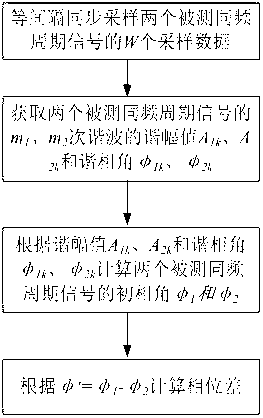
Method for measuring common-frequency periodic signal phase differences
A technology of periodic signal and measurement method, which is applied in the field of measurement and can solve the problems of unguaranteed measurement accuracy and difficulty.
- Summary
- Abstract
- Description
- Claims
- Application Information
AI Technical Summary
Problems solved by technology
Method used
Image


Examples
Embodiment 1
[0042] Embodiment 1: nuclear phase instrument
[0043] The phase nuclear instrument is used in the phase verification and phase sequence verification of power lines and substations, and has the functions of phase verification, phase sequence measurement and electric inspection.
[0044] The nuclear phase instrument is mainly composed of sensors, signal conditioning circuits, data acquisition circuits, CPU and corresponding analysis software. The sensor generally uses a voltage transformer to convert the high-voltage signals of the two high-voltage lines under test at a certain ratio; the signal conditioning circuit converts the voltage signal sent by the sensor into a voltage signal suitable for sampling by the acquisition circuit; the data acquisition circuit will condition The final signal is sampled, and then the analysis software is used to complete the analysis and judgment of the phase sequence and phase difference of the two high-voltage lines. The specific measurement...
Embodiment 2
[0050] Embodiment 2: MOA resistive current tester and MOA resistive current online monitoring device
[0051] Metal oxide surge arresters (hereinafter referred to as MOA) are widely used in power systems due to their superior overvoltage protection characteristics, but the aging of MOA resistors and thermal and impact damage will cause failures, which may lead to explosions and arrester breakdown It will also lead to a short circuit of the substation bus and affect the safe operation of the system. Therefore, strict and effective detection and regular preventive tests must be carried out on the running MOA. In the detection and test of zinc oxide arresters, the measurement of leakage current under AC operating voltage is an important item. The size of the resistive current fundamental wave component in the leakage current can more accurately reflect the dampness of the zinc oxide arrester and the aging of the valve plate. and internal insulation damage and other defects. Ther...
Embodiment 3
[0055] Embodiment 3: Dielectric loss current tester
[0056] The dielectric loss tester is a high-precision instrument for fully automatic measurement of the dielectric loss tangent and capacitance of various high-voltage power equipment in power plants and substations. Under the action of AC voltage, the dielectric will consume part of the electric energy, which will be converted into heat energy and lost. This energy loss is called dielectric loss. When an AC voltage is applied to the dielectric, there is a phase angle difference between the voltage and the current in the dielectric The complementary angle δ is called the dielectric loss angle, and the tangent tanδ of δ is called the dielectric loss tangent. The tanδ value is a parameter used to measure dielectric loss. The specific measurement process is as follows: (1) Synchronously sample the voltage signal V applied on the test piece and the current signal I flowing; (2) Apply harmonic analysis technology to obtain t...
PUM
 Abstract
Description
Claims
Application Information