Regulating and controlling system of optical glass set

A technology of optical lens and control system, which is applied in the field of optical lens group, can solve problems such as damage to optical elements, operator injury, time-consuming and labor-consuming, etc., and achieve the effects of improving efficiency, high operating efficiency, and good operating safety

Active Publication Date: 2013-08-21
如东文园投资开发有限公司
View PDF5 Cites 7 Cited by
  • Summary
  • Abstract
  • Description
  • Claims
  • Application Information

AI Technical Summary

Problems solved by technology

[0002] The optical lens group is composed of multiple optical lenses, which regulate the characteristics of the optical path and complete the functions of optical imaging, detection or manufacturing; in large-scale optical path systems, such as femtosecond laser systems, each optical lens is generally passed through The seats are scattered and fixed on the vibration isolation table, and the fine-tuning of the laser optical path is realized by adjusting the lifting height and rotation angle of a single lens; when debugging the optical path, it is often necessary to adjust multiple lenses at the same time to achieve the adjustment effect, especially when the optical path The system is more complicated, there are many optical lenses that need to be adjusted, and when the spatial distribution of the lenses is scattered, it will be very time-consuming and labor-intensive to adjust the optical path manually by the operator; because it cannot be accurately quantified, the manual method requires the operator to have better In addition, the manual method often brings some safety hazards; for example, the operator is injured due to blocking the optical path, and the optical components are damaged due to collisions, etc.

Method used


Image

  • Regulating and controlling system of optical glass set
  • Regulating and controlling system of optical glass set
  • Regulating and controlling system of optical glass set

Examples


Embodiment Construction

[0026] The specific embodiments of the present invention will be further described below in conjunction with the accompanying drawings.

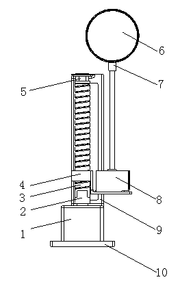
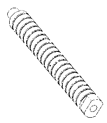
[0027] figure 1 Single optical lens adjustment structure assembly diagram; it mainly consists of stepping motor 1, coupling 2, screw rod 3, stepped nut 4, screw cover 5, optical lens 6, optical lens cover 7, second stepping motor 8. The support frame 9 is composed of a fixed base 10; wherein, the stepping motor 1 is a 17HS5604 motor; the stepping motor 8 is a 28BYJ48 long-axis stepping motor.

[0028] The step angle of the first stepper motor (model 17HS5604) is 1.8° (motor parameters), that is, every time a pulse is given to the 17HS5604 stepper motor, the stepper motor will rotate 1.8°; the motor speed is 60r / min (SCM program control value, variable and adjustable), that is, 1r / s; the lead of the screw is 3mm (every time the screw rotates, that is, 360°, the nut will rise or fall by 3mm); when a pulse is given to the stepping motor, the s...


PUM


Abstract

The invention relates to an optical glass group, in particular to a regulating and controlling system of the optical glass set. The regulating and controlling system of the optical glass set comprises a single chip microcomputer, stepping motors, a coupler, a screw rod, a step-shaped nut, a support, an optical glass and a fixed base, wherein a first stepping motor is fixed on the fixed base, the lower end of the support is fixed on the first stepping motor, an output shaft of the first stepping motor is connected with the bottom end of the screw rod through the coupler, the screw rod is vertically arranged, and a screw rod sleeve is sleeved at the top end of the screw rod and is embedded into a round hole of the top end of the support simultaneously. A threaded hole is formed in an upper step of the step-shaped nut and sleeved between the bottom end of the screw rod and the top end of the screw rod, a lower step of the step-shaped nut is arranged beside the screw rod, a second stepping motor is fixed on the lower step of the step-shaped nut, and the output shaft of the second stepping motor is connected with the optical glass through an optical glass sleeve. The single chip microcomputer is used for controlling the first stepping motor and the second stepping motor. The regulating and the controlling system of the optical glass set enables an operator to be far away from an optical path system so that concentrate regulation and control can be conducted and efficiency and precision of the regulation and control and safety of operation can be improved.

Description

technical field [0001] The invention relates to an optical lens group, in particular to a system capable of regulating the lifting height and rotation angle of each lens in the optical lens group based on the control principle of a single-chip microcomputer. Background technique [0002] The optical lens group is composed of multiple optical lenses, which regulate the characteristics of the optical path and complete the functions of optical imaging, detection or manufacturing; in large-scale optical path systems, such as femtosecond laser systems, each optical lens is generally passed through The seats are scattered and fixed on the vibration isolation table, and the fine-tuning of the laser optical path is realized by adjusting the lifting height and rotation angle of a single lens; when debugging the optical path, it is often necessary to adjust multiple lenses at the same time to achieve the adjustment effect, especially when the optical path The system is more complicate...

Claims


Application Information

Patent Timeline
Patent Type & Authority Applications(China)
IPC IPC(8): G02B7/00G05D3/00
Inventor 坎标高杰丁建宁刘海
Owner 如东文园投资开发有限公司
Why Eureka
Try Eureka