Plasma jet device with suspension electrode

A plasma and jet device technology, applied in the field of plasma, can solve the problem of low density of active particles, and achieve the effects of reducing breakdown voltage, easy ionization, and increasing cross-sectional area

Inactive Publication Date: 2013-08-21
HUAZHONG UNIV OF SCI & TECH
View PDF3 Cites 25 Cited by
  • Summary
  • Abstract
  • Description
  • Claims
  • Application Information

AI Technical Summary

Problems solved by technology

[0005] Aiming at the defects of the prior art, the object of the present invention is to provide a plasma jet device with suspended electrodes, aiming to solve the problem of low density of active particles in the prior art

Method used


Image

  • Plasma jet device with suspension electrode
  • Plasma jet device with suspension electrode
  • Plasma jet device with suspension electrode

Examples


Embodiment 1

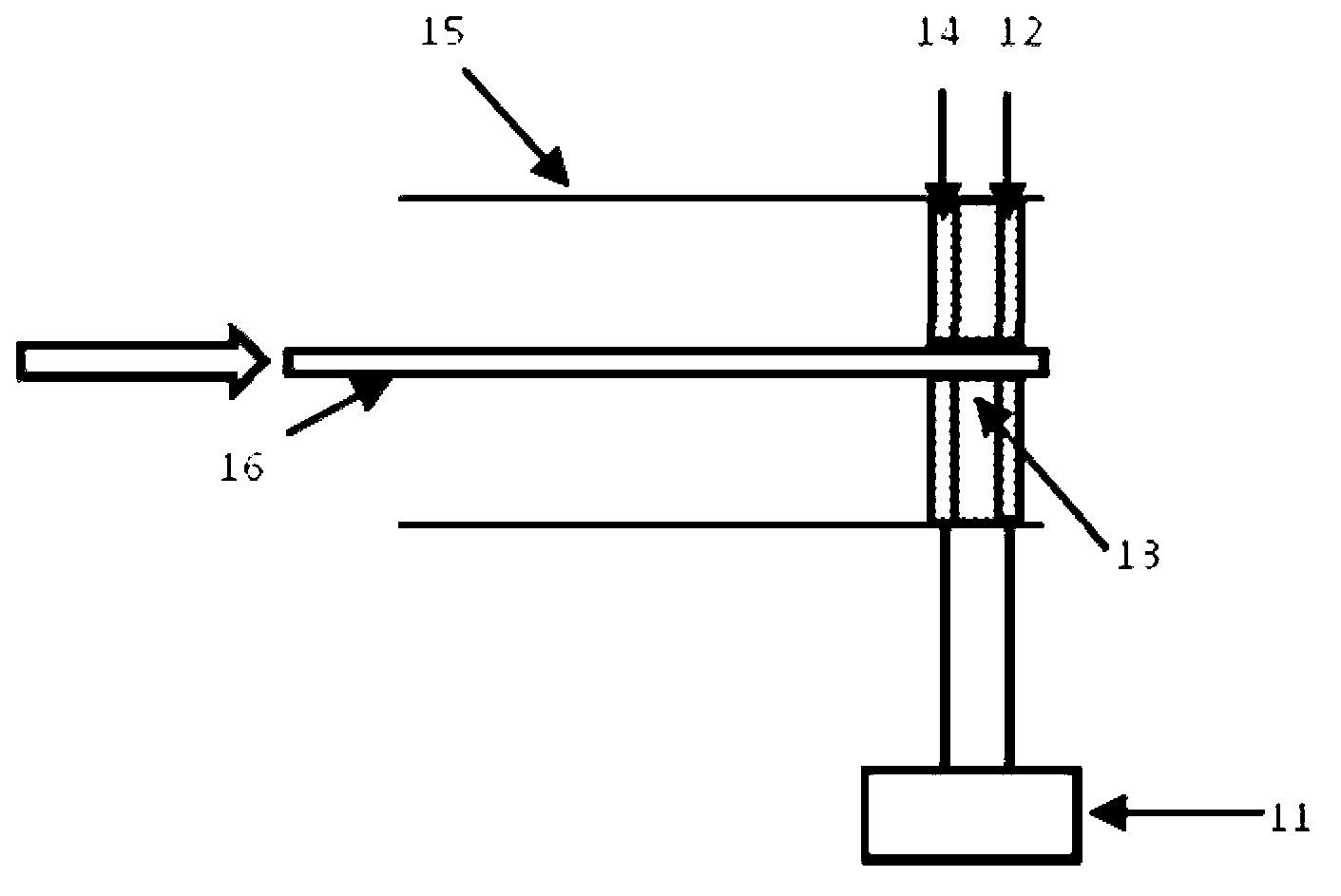
[0038] Embodiment 1: as Figure 4 As shown, the plasma jet device includes a dielectric tube 2, a suspension electrode 1, a high-voltage electrode 3, a vent 10, a working gas 12, and a pressure reducing valve 11. The dielectric tube 2 is a quartz tube or a glass tube with openings at both ends, with an inner diameter of 8 The suspension electrode 1 is a stainless steel needle, and the high-voltage electrode 3 is closely attached to the outer wall of the medium tube. The power supply 6 is a pulse power supply, and the power supply 6 is connected to the high-voltage electrode 3. The working gas 12 enters from the vent 10 through the pressure reducing valve 11, flows out through the medium pipe 2, and generates plasma 4 on the other side of the medium pipe. The working gas can be simple gas such as helium, argon, nitrogen, oxygen, or a mixed gas mixed with other gases, or it can be air, gaseous compounds, or gaseous organic compounds.

[0039] Existing plasma jet devices current...

Embodiment 2

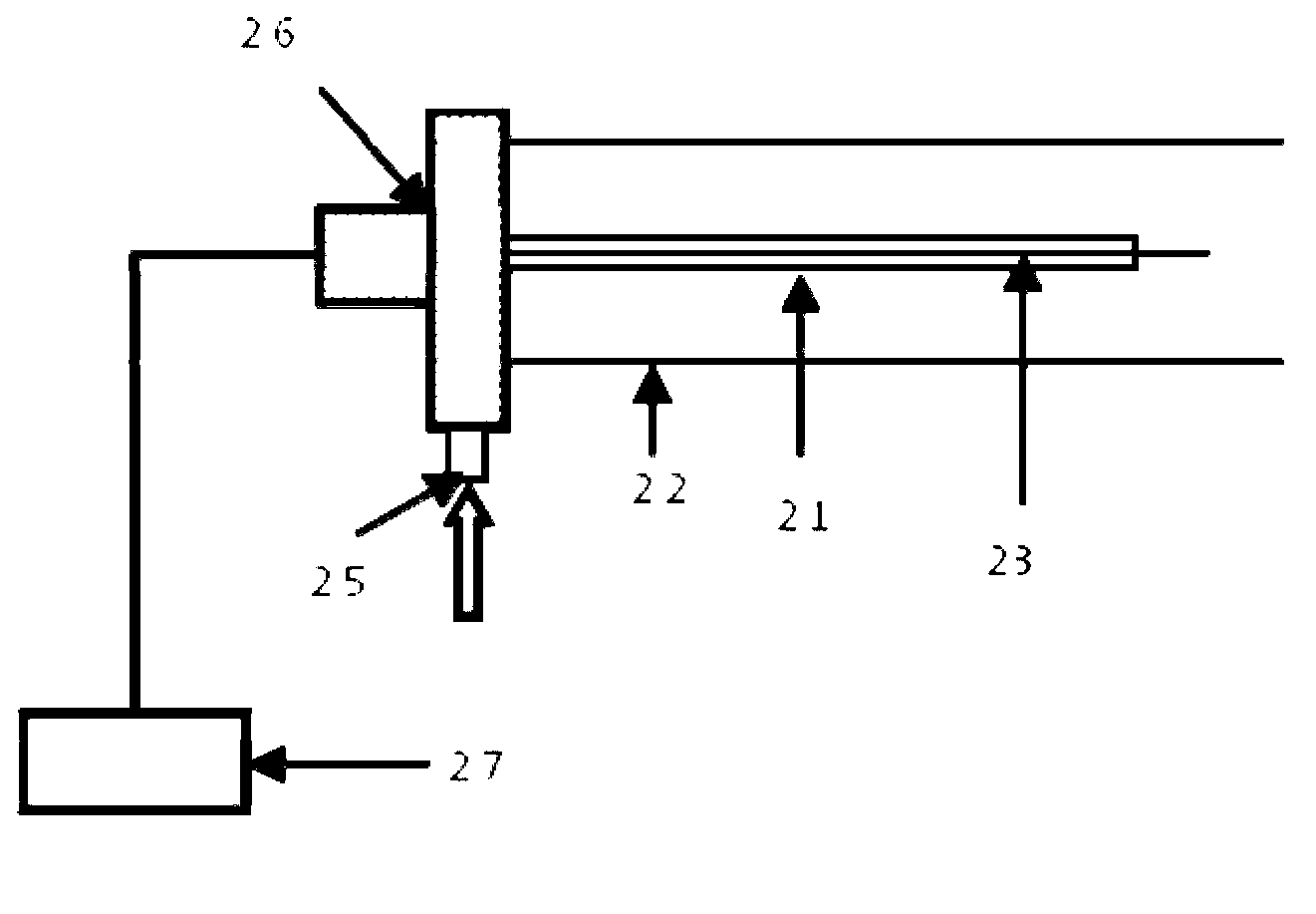
[0040]Embodiment 2: as Figure 5 As shown, the parameters of the dielectric tube 2, the high-voltage electrode 3, and the pulse power supply 6 are the same as those in Example 1. The suspension electrode unit 1 is composed of a suspension electrode and a glass tube sealed at one end. The suspension electrode is a copper wire and is located in the glass tube; the suspension electrode unit uses With the above structure, the insulating medium is inserted into the discharge space to form a dielectric barrier discharge. This suspension electrode device not only has the advantages of Embodiment 1, but also can increase the cross-sectional area of ​​the plasma, thereby increasing the processing capacity in material processing and biomedical applications. area. Due to the use of glass or ceramics as the dielectric barrier discharge, the temperature of the plasma is low, generally room temperature or slightly higher than room temperature.

[0041] Taking helium as an example, the diam...


PUM


Abstract

The invention belongs to the technical field of plasma, and provides a plasma jet device with a suspension electrode. The plasma jet device comprises a medium pipe, an air port, the suspension electrode, a supporting structure, a high-voltage electrode and a work power supply, wherein two ends of the medium pipe are open, the air port is sleeved at the inlet end of the medium pipe, the suspension electrode is suspended inside the medium pipe, the supporting structure is used for supporting the suspension electrode, the high-voltage electrode is wrapped at the outlet end of the medium pipe, and the work power supply is connected with the high-voltage electrode. When the plasma jet device works, work air flows into the plasma jet device through the air port and flows out through the outlet end of the medium pipe, and the plasma jet with high-density active particles is generated. According to the plasma jet device, the conical degree of the head of a needle electrode is high, a strong electric field can be formed, ionization occurs more easily, and therefore breakdown voltage can be effectively reduced, and the active particles can be ionized more easily. The problem that the active particles in the prior art are low in density is resolved, the area of the cross section of the plasma can also be enlarged, and therefore the processing area can be enlarged in material processing and biological application.

Description

technical field [0001] The invention belongs to the field of plasma technology, and more specifically relates to a plasma jet device with suspended electrodes. Background technique [0002] Existing plasma jet device can be divided into following several kinds: the first such as figure 1 A plasma generator with a kilohertz AC power supply is shown, including a high-voltage electrode 14 and a ground electrode 12 separated by a dielectric disc 13, and they are placed together in a dielectric tube 15. The working gas source 16 is nitrogen, and the flow rate is 3 liters. / Second. The working power source 11 is a high-voltage AC power source with a frequency of 20 kHz. Plasma is ejected from the tube through small holes in the electrodes and dielectric disc. The second such as figure 2 In the radio frequency plasma needle shown, the working power supply 27 is a radio frequency power supply, and a tungsten wire with a diameter of 0.3 mm is connected to the radio frequency pow...

Claims


Application Information

Patent Timeline
Patent Type & Authority Applications(China)
IPC IPC(8): H05H1/26
Inventor 刘大伟胡江天卢新培
Owner HUAZHONG UNIV OF SCI & TECH
Why Eureka
Try Eureka