Laser surfacing modification method for thermal barrier coating

A technology of laser surface modification and thermal barrier coating, applied in the direction of coating, metal material coating process, climate sustainability, etc., can solve the problems of large residual stress, interdiffusion and dilution between bonding layer and ceramic layer, etc. , to improve the structure of the coating, reduce the stress of laser modification, and improve the surface roughness of the coating

Active Publication Date: 2013-08-28
FOSHAN TAOYUAN INST OF ADVANCED MFG
View PDF5 Cites 13 Cited by
  • Summary
  • Abstract
  • Description
  • Claims
  • Application Information

AI Technical Summary

Problems solved by technology

However, the current laser surface modification method of thermal barrier coatings still has some disadvantages: on the one hand, the overall laser remelting of thermal barrier coatings can improve the coating density and bonding strength, but it will also produce bonding layers and ceramics. layer interdiffusion and dilution; on the other hand, the laser remelting of the surface layer of the ceramic layer can reduce the crack rate and prevent the ceramic layer from being diluted by the bonding layer, but it will inevitably introduce new interfaces in the ceramic layer, resulting in large Residual stress, and this method is meaningless to improve the bonding strength between the ceramic layer and the bonding layer

Method used


Image

  • Laser surfacing modification method for thermal barrier coating
  • Laser surfacing modification method for thermal barrier coating
  • Laser surfacing modification method for thermal barrier coating

Examples


Embodiment 1

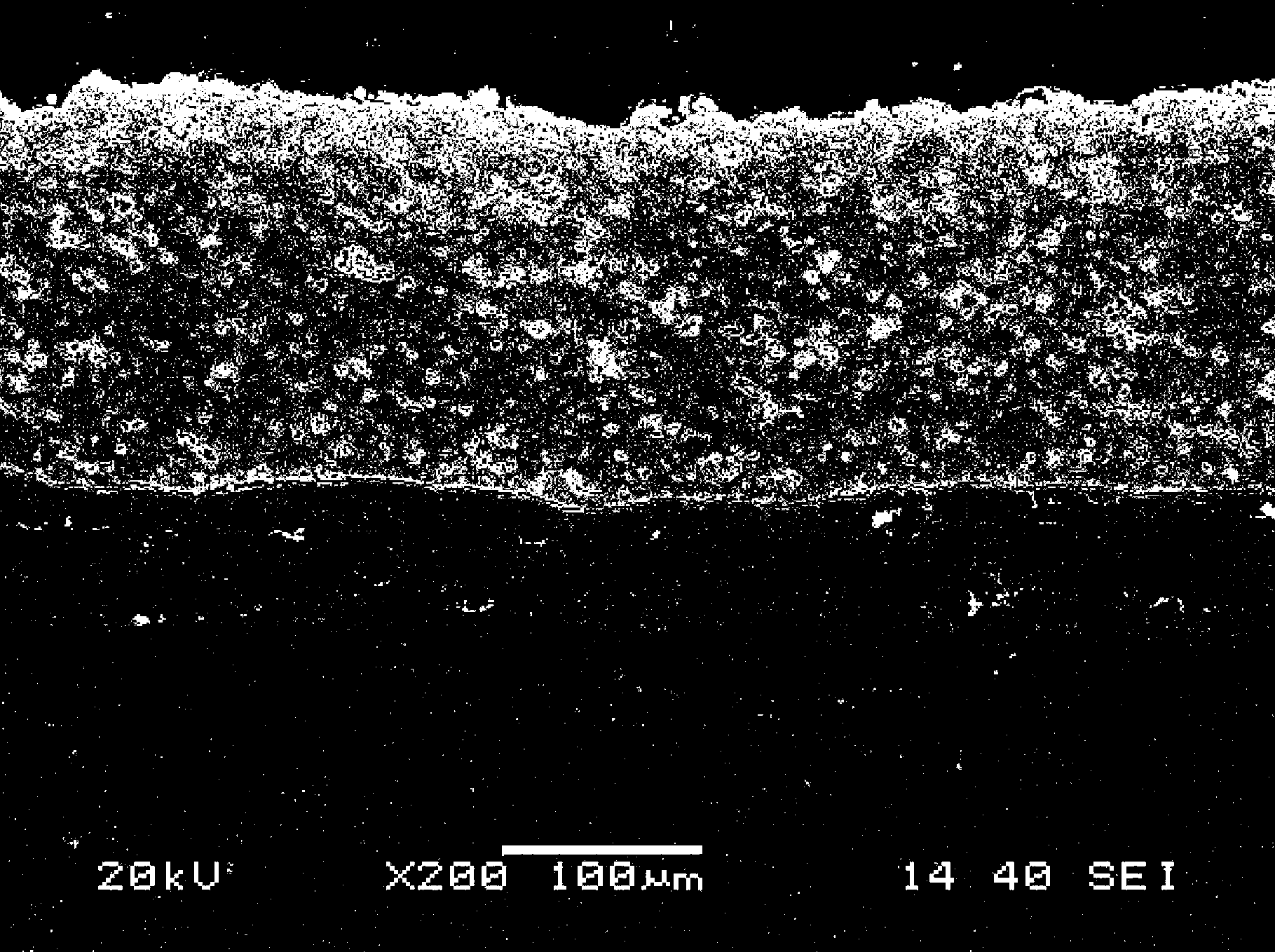
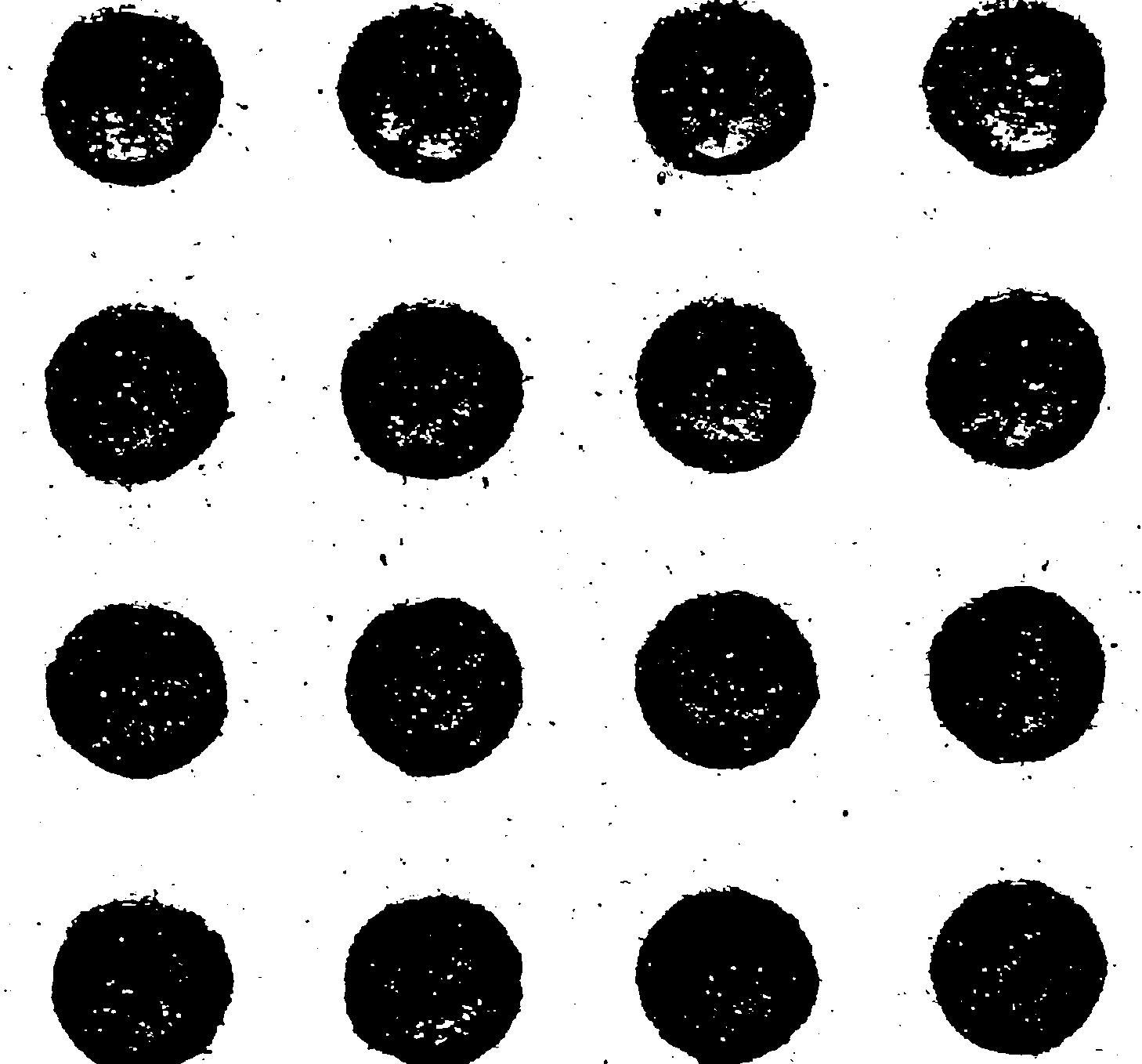
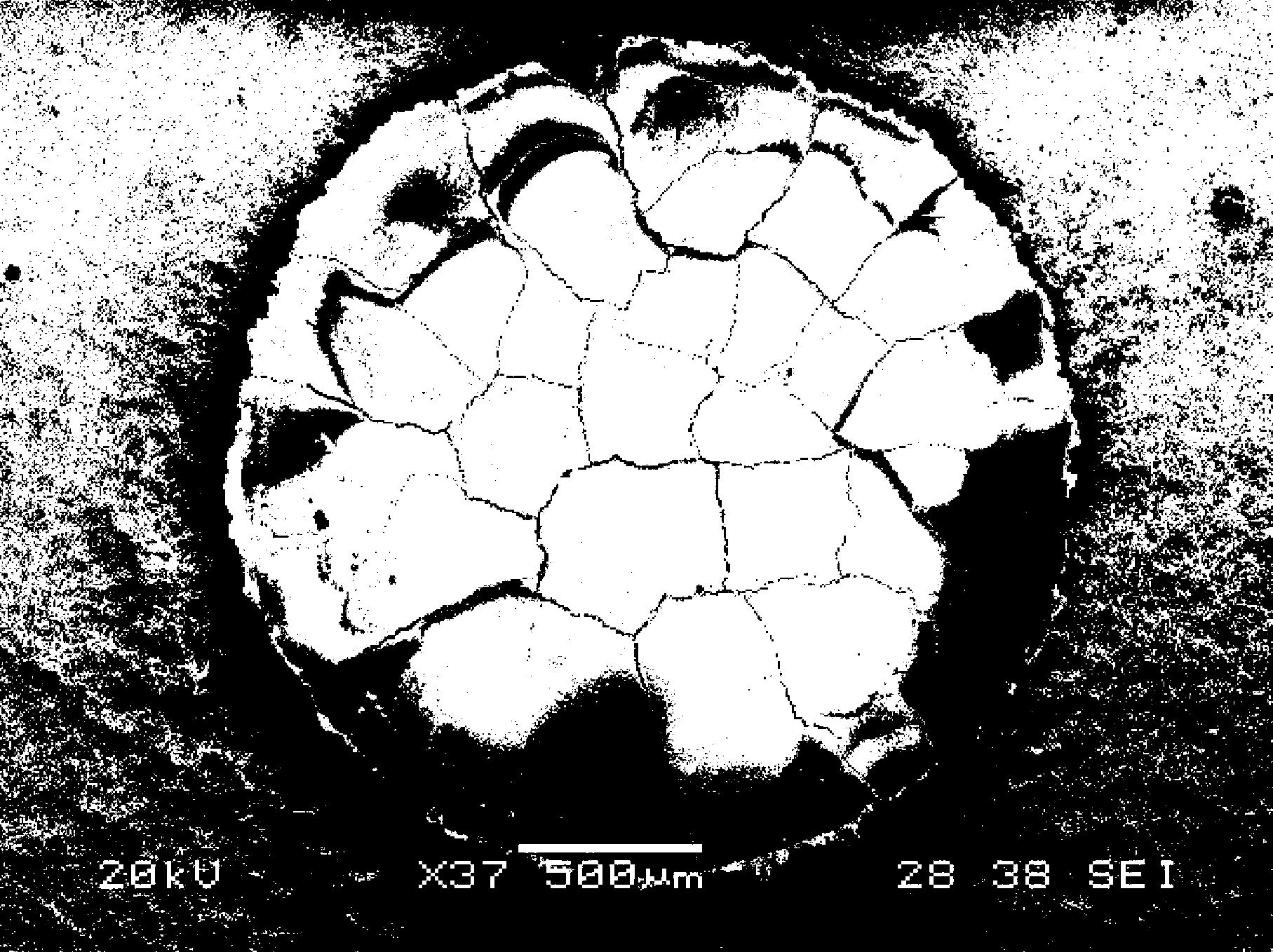
[0028] First, the GH4169 superalloy substrate is cleaned and sandblasted according to the conventional process; then, a thermal sprayed thermal barrier coating is prepared on the surface of the substrate. Since the thermal barrier coating is composed of a ceramic layer and a bonding layer, the fabrication In this case, a NiCoCrAlYTa bonding layer with a thickness of about 60 μm was first prepared by supersonic spraying, and then a 7% yttrium oxide partially stabilized zirconia ceramic layer with a thickness of about 200 μm was prepared by atmospheric plasma spraying. The cross-sectional shape is as figure 1 As shown; then, the peg structure laser modified unit body is designed by computer and design software, the peg structure laser modified unit body is an inverted spherical crown unit body, and the exposed surface of the inverted spherical crown unit body is a circle shape, the diameter of the circular surface of the inverted spherical crown unit is 2 mm, the height of the i...

Embodiment 2

[0030]First, the GH4169 superalloy substrate is cleaned and sandblasted according to the conventional process; a thermally sprayed thermal barrier coating is prepared on the surface of the substrate. Since the thermal barrier coating is composed of a ceramic layer and a bonding layer, when making it, First, a NiCoCrAlYTa bonding layer with a thickness of about 100 μm was prepared by low-pressure plasma spraying, and then a 7% yttrium oxide partially stabilized zirconia ceramic layer with a thickness of about 300 μm was prepared by atmospheric plasma spraying; then, the pile nail structure was designed by computer and design software. Modified unit body, the design of the peg structure laser modified unit body is completed by computer and design software, the peg structure laser modified unit body is an inverted spherical crown unit body, and the exposed spherical crown unit body The surface is circular, the diameter of the circular surface of the inverted spherical crown unit i...


PUM

PropertyMeasurementUnit
heightaaaaaaaaaa
thicknessaaaaaaaaaa
thicknessaaaaaaaaaa

Abstract

The invention relates to a laser surfacing modification method for a thermal barrier coating. The method comprises the following steps of: firstly, carrying out washing and sand blasting on the surface of a base body; then, preparing the thermal barrier coating in a thermal spraying state on the surface of the base body; then, designing shape, size, arrangement rule and distribution density of laser modification unit bodies in a pile nail structure to be prepared in the thermal barrier coating; then, adjusting the process parameters of a laser according to a design model; then, performing laser modification to the thermal barrier coating; and finally, performing the stress relief annealing treatment to the laser modified thermal barrier coating. With the adoption of the method for arranging discontinuous and dispersed intensifying unit bodies in the pile nail structure in the thermal barrier coating, the thermal barrier coating can not only generate characteristic of soft and hard alternate change, but also generate the 'pinning effect', thus not only relieving stress concentration at the crack tip of the coating and reducing the crack rate of the coating, but also extremely improving the bonding strength of the coatings, prolonging the thermal fatigue service life of the thermal barrier coating, improving the tissue structure of the coating and improving the compactness of the coating.

Description

technical field [0001] The invention belongs to the technical field of preparation and modification of thermal barrier coatings, and in particular relates to a laser surface modification method of thermal barrier coatings with the structural characteristics of piles and nails. Background technique [0002] Thermal barrier coating is a thermal protection technology that coats high temperature resistant and high heat insulation materials on the surface of the base alloy to improve the high temperature resistance of the base alloy and reduce its surface temperature. Thermal barrier coatings not only have broad application prospects in the fields of ships and energy, but are also an essential key technology for the development of next-generation aero-engines. With the development of aero-engines to high thrust-to-weight ratios, the design inlet temperature of the engines continues to increase, and the use of high-temperature structural materials alone cannot meet the design requ...

Claims


Application Information

Patent Timeline
Patent Type & Authority Applications(China)
IPC IPC(8): C23C4/18C23C4/10C23C4/11
CPCY02T50/60
Inventor 佟鑫周克崧常发刘敏代明江邓畅光
Owner FOSHAN TAOYUAN INST OF ADVANCED MFG
Why Eureka
Try Eureka