
Control method of marine SCR (selective catalytic reduction) system

A technology of SCR system and control method, which is applied to the electric control of exhaust treatment devices, exhaust treatment, mechanical equipment, etc., and can solve the problems of poor real-time performance and dynamic stability, drift of NOx conversion rate, low anti-interference ability, etc. , to achieve the effect of convenient application maintenance, superior stability and fast response speed

Active Publication Date: 2015-04-15
上海齐耀环保科技有限公司
View PDF6 Cites 0 Cited by
  • Summary
  • Abstract
  • Description
  • Claims
  • Application Information

AI Technical Summary

Problems solved by technology

[0004] 1. The operating conditions of many marine diesel engines will often change, resulting in a difference between the NOx emissions generated during the operation of the diesel engine and the NOx amount in the MAP chart established under steady-state operating conditions, resulting in injection errors;
[0005] 2. The pyrolysis efficiency of the urea solution will change with the temperature of the exhaust pipe. This change will lead to a large deviation between the effective decomposition amount of the urea solution and the actual injection amount, resulting in a drift of the NOx conversion rate. It may even cause relatively large NH3 leakage at the outlet of the reactor;
[0006] 3. This method relies on the diesel engine body control system to obtain working condition signals, and cannot be effectively applied to diesel engines whose control system interfaces are not open;
[0007] 4. The establishment of the MAP diagram in this method requires a lot of manpower and material support, and the aging loss of the device cannot be effectively followed up during the operation process, the real-time performance and dynamic stability are poor, the anti-interference ability is low, and it is not easy to upgrade the product

Method used


Image

  • Control method of marine SCR (selective catalytic reduction) system
  • Control method of marine SCR (selective catalytic reduction) system
  • Control method of marine SCR (selective catalytic reduction) system

Examples


Embodiment Construction

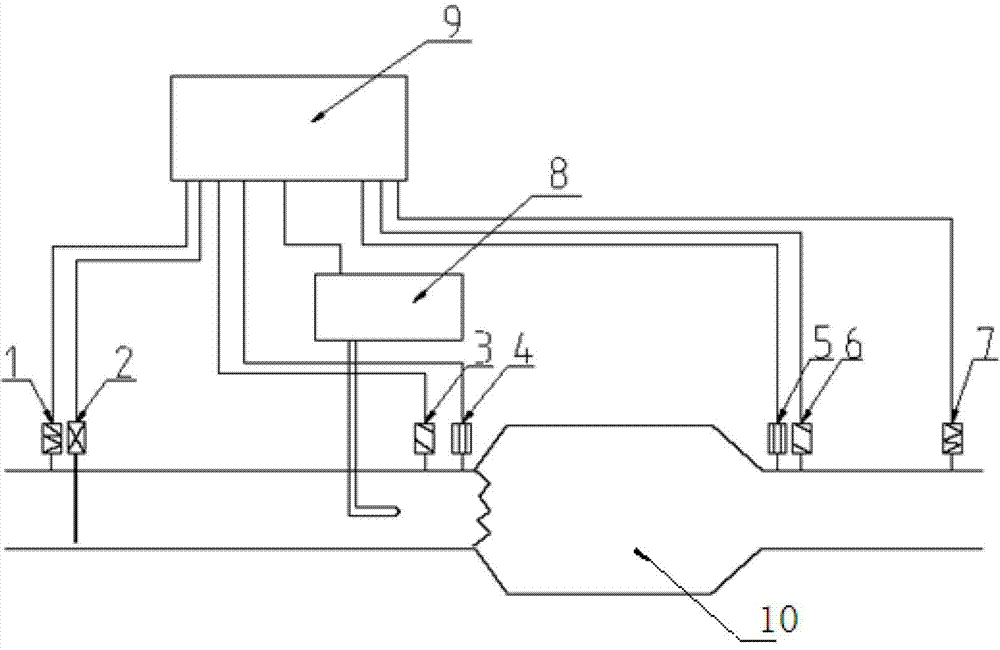
[0029] See attached figure 2 , 3 , a control method for a marine SCR system, which is based on the SCR system. The layout of the SCR system is as follows: on the exhaust pipe in front of the SCR catalyst 10, a temperature sensor A1, an exhaust flow mass sensor 2, an injection device 8, A pressure sensor A3 and a nitrogen oxide sensor A4, a nitrogen oxide sensor B5, a pressure sensor B6 and a temperature sensor B7 are arranged in sequence on the exhaust pipe behind the SCR catalyst 10;

[0030] Connect the temperature sensor A1, the exhaust flow mass sensor 2, the injection device 8, the pressure sensor A3, the nitrogen oxide sensor A4, the nitrogen oxide sensor B5, the pressure sensor B6 and the temperature sensor B7 to the PID controller 9 respectively;

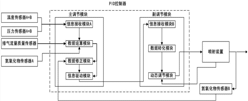
[0031] The PID controller 9 is set, and the main adjustment module and the auxiliary adjustment module are set in the PID controller 9; wherein, the main adjustment module includes an information receiving module A, a data...


PUM


Abstract

The invention belongs to the technical field of controlling emission pollution of nitric oxide in diesel engine exhaust and particularly relates to an active control method of a marine SCR (selective catalytic reduction) system. According to the technical scheme, the control method includes: sequentially setting a temperature sensor A (1), an exhaust flow mass sensor (2), an injection device (8), a pressure sensor A (3) and a nitric oxide sensor A (4) on an exhaust pipe in front of an SCR catalyst (10); sequentially setting a nitric oxide sensor B (5), a pressure sensor B (6) and a temperature sensor B (7) on an exhaust pipe behind the SCR catalyst (10); measuring signals of temperature, exhaust mass flow, pressure, nitric oxide concentration and the like; using an PID (proportion integration differentiation) controller to process the signals before inputting the signals to a main regulating module and an auxiliary regulating module; and performing closed-loop control by an algorithm. The control method allows for self-optimization of NOX emission conversion rate of the SCR system and has the advantages of full adaptation, fast response, fine convergence performance, excellent stability and convenience in application and maintenance.

Description

technical field [0001] The invention belongs to the technical field of diesel engine tail gas nitrogen oxide emission pollution control, and in particular relates to an active control method for a marine SCR system. Background technique [0002] Selective Catalytic Reduction (SCR) is the mainstream technology for marine diesel engine nitrogen oxide (NOx) emission treatment. At present, the control method of domestic and foreign marine SCR systems is the MAP algorithm. The algorithm flow chart is as follows figure 1 shown. By comparing the diesel engine operating condition signal with the MAP map, the NOx content in the exhaust gas can be obtained, and then the volume of the urea solution to be injected is calculated according to the NOx conversion rate preset by the system, and finally the urea solution is injected into the A control cycle is completed in the exhaust pipe. [0003] In the actual application process, this control method has the following disadvantages: [...

Claims


Application Information

Patent Timeline
Patent Type & Authority Patents(China)
IPC IPC(8): F01N9/00F01N3/20
CPCY02T10/24Y02T10/47Y02T10/12Y02T10/40
Inventor 姜小鑫沈飞翔耿见宇李晓波刘娅琼任中沈忆闽
Owner 上海齐耀环保科技有限公司
Features
  • Generate Ideas
  • Intellectual Property
  • Life Sciences
  • Materials
  • Tech Scout
  • Unparalleled Data Quality
  • Higher Quality Content
  • 60% Fewer Hallucinations
Learn More