Energy-saving boiler

A technology for boilers and heating furnaces, applied in the field of boilers, which can solve the problems of poor utilization of waste gas heat energy, insufficient combustion of fuel, and insufficient use of heat energy, etc., to achieve the effects of saving resources, sufficient combustion, and shortening heating time

Active Publication Date: 2013-08-28
ZHEJIANG DONGDU ENERGY SAVING TECH
View PDF5 Cites 3 Cited by
  • Summary
  • Abstract
  • Description
  • Claims
  • Application Information

AI Technical Summary

Problems solved by technology

[0003] At present, most of the boilers are single-body structure, and the water is stored in the outer cavity of the combustion chamber. The exhaust gas passage is relatively short, and the residence time is relatively short, resulting in a large amount of heat that is not fully utilized, and is discharged through the exhaust port, which is not well utilized. The thermal energy in the exhaust gas causes a lot of thermal energy waste in the exhaust gas, which makes the temperature rise of the water in the furnace slower, and a large amount of heat energy is taken away by waste and dust, which wastes energy, and because the exhaust gas and dust after burning coal and other fuels are directly It is discharged into the atmosphere through an external chimney, which greatly pollutes the environment and wastes resources
Today, when energy conservation and emission reduction are advocated, people have carried out various modifications to boilers, but there are problems such as insufficient combustion of fuel, insufficient use of heat energy, and serious air pollution.

Method used


Image

  • Energy-saving boiler
  • Energy-saving boiler
  • Energy-saving boiler

Examples


Embodiment Construction

[0020] The present invention will be described in further detail below in combination with the accompanying drawings, and specific implementation methods will be given.

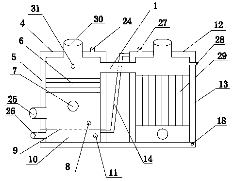
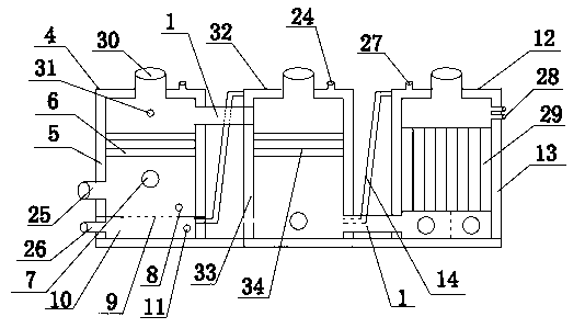
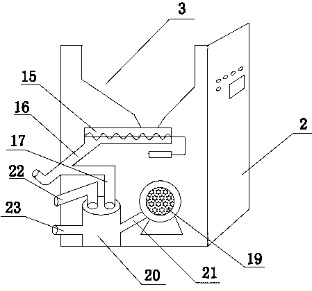
[0021] As shown in the figure, an energy-saving boiler of the present invention includes a feeding blast device and a heating device. The heating device includes a heating furnace and a preheating furnace. The feeding blast device is connected with the heating furnace to send fuel into the heating furnace for combustion. , the heating furnace and the preheating furnace are connected through the fire passage 1 arranged on the upper part of the furnace body, the feeding blast device is arranged in the box body 2 with a control panel, and the upper part of the box body 2 is provided with a silo 3, and the silo 3 The lower part is provided with a feeding blast device, which includes a feeding hinged wheel 15 and a blowing system used in conjunction with the material bin 3, and the feeding hinged wheel 15 is arrang...


PUM


Abstract

The invention discloses an energy-saving boiler, and belongs to the technical field of boilers. The energy-saving boiler comprises a feeding blower device and a heating device. The heating device comprises a heating furnace and a pre-heating furnace. The feeding blower device comprises a feeding hinged wheel and a blower system, wherein the feeding hinged wheel is used with a stock bin in a matched mode. A discharging pipe is placed at one end of the feeding hinged wheel, and a fuel blast pipe is arranged on the discharging pipe which is connected with a fuel inlet in a matching mode. A water inlet is formed in the lower portion of a pre-heating furnace body and is communicated with a cold water sleeve. Fuel can be fully mixed with oxygen before entering a boiler furnace through the arrangement of a material feeding device, and the burn-off rate of the fuel is improved. Cold water is heated in advance through the pre-heating furnace body, the reserved time of exhausted gas is prolonged, thermal conversion efficiency is improved, resources are saved, and heating time is shortened. A smoke journey is lengthened through heating pipes which are connected in series, the thermal energy is fully absorbed by the water, and the circulation of the water in the boiler water sleeve is accelerated. Meanwhile, enough time is reserved for the ash in smoke to fall down into an ash discharging chamber, air pollution is reduced, energy is saved, and environment is protected.

Description

technical field [0001] The invention belongs to the technical field of boilers, and in particular relates to an energy-saving boiler. Background technique [0002] Boilers are indispensable equipment for heating and heating in civil or industrial use. Traditional boilers only heat the water in the interlayer by directly heating the inner wall of the boiler. The fuel usually uses coal, gas, oil and other mineral energy. The supply of non-renewable fossil fuels is shrinking sharply, and their supply is becoming increasingly tight, while fuel prices are also rising. Adopt the above-mentioned fuel to have the defect of high pollution and waste of energy in addition. Biomass fuel, as an alternative energy source from renewable resources, can improve the environment and reduce CO in the atmosphere 2 content and reducing the "greenhouse effect" are of great benefit, and are gradually being utilized. As a large agricultural country, our country is rich in biomass resources. Accord...

Claims


Application Information

Patent Timeline
Patent Type & Authority Applications(China)
IPC IPC(8): F24H1/28F24H9/14
Inventor 梁达安
Owner ZHEJIANG DONGDU ENERGY SAVING TECH
Why Eureka
Try Eureka