Vertical Turbocharger

A turbocharger, vertical technology, applied in the direction of machine/engine, engine components, internal combustion piston engine, etc., can solve the problems of complex control system, complex air passage, unfavorable layout, etc., to achieve low noise and improve mechanical efficiency , the effect of improving the rotor dynamic performance

Active Publication Date: 2015-09-09
BEIJING INSTITUTE OF TECHNOLOGYGY
View PDF3 Cites 0 Cited by
  • Summary
  • Abstract
  • Description
  • Claims
  • Application Information

AI Technical Summary

Problems solved by technology

The most common two-stage supercharging system adopts a structure in which two turbochargers and a diesel engine are connected in series on the gas path, which is bulky and unfavorable for its arrangement in the vehicle power compartment; moreover, the airflow channel is complicated, the flow loss is large, and the control system is complex , high cost, poor reliability

Method used


Image

  • Vertical Turbocharger
  • Vertical Turbocharger
  • Vertical Turbocharger

Examples


no. 1 example

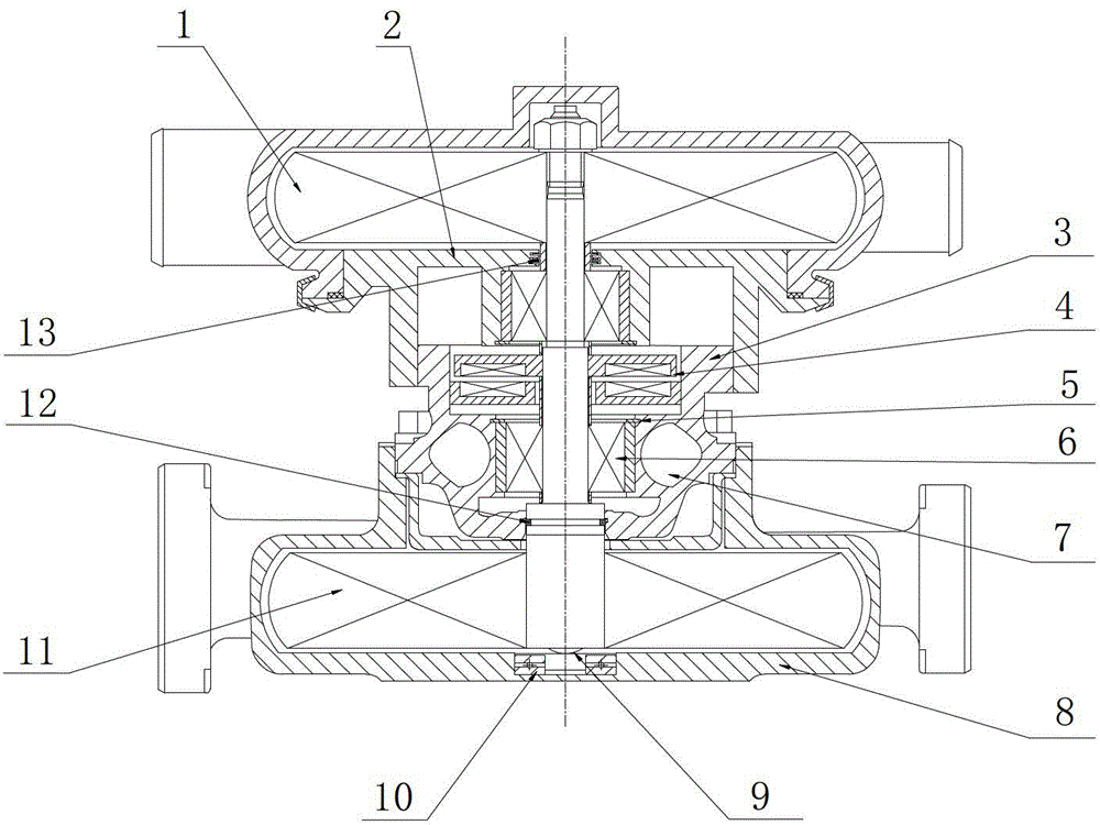
[0034]figure 1 It is a structural diagram of the first embodiment of the vertical turbocharger of the present invention. The non-liquid oil lubricated bearing used in this embodiment is an electromagnetic bearing, including a radial electromagnetic bearing 6 and an axial electromagnetic bearing 4, such as figure 1 shown. The rotor shaft of the vertical turbocharger is arranged vertically to the ground, and the compressor and the turbine are respectively arranged at the upper end and the lower end of the rotor shaft. In the present invention, the rotor shaft is vertically arranged, so the lower end of the rotor shaft and the An axial thrust bearing 10 is provided at the matching place of the turbine casing 8 of the turbine for carrying axial force. Preferably, in order to reduce the friction between the rotor shaft and the axial thrust bearing 10 when it rotates, the top of the lower end of the rotor shaft is provided with a spherical center 9 structure to cooperate with the a...

no. 2 example

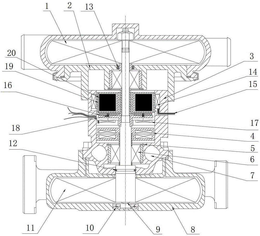
[0036] figure 2 It is a structural diagram of the second embodiment of the vertical turbocharger of the present invention. Such as figure 2 As shown, further, in order to solve the problem of "turbo lag" of the turbocharger, improve the utilization rate of exhaust gas energy, and improve the economical efficiency of the engine, the intermediate body 3 of the vertical turbocharger and the compressed air in this embodiment A motor generator and a clutch device are arranged between the motors, and both the motor generator and the clutch device are arranged around the rotor shaft, and the motor generator can be combined and separated from the rotor shaft through the clutch device. When the engine starts, accelerates or operates at low speed, the motor-generator rotor 20 is combined with the rotor shaft through the clutch device, the motor-generator rotor 20 and the turbine drive the coaxial compressor to rotate together, and the motor-generator acts as a motor to drive the roto...

no. 3 example

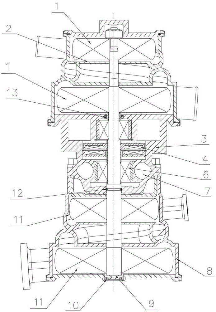
[0039] In the first embodiment and the second embodiment, the compressor and the turbine are respectively a first-stage compressor and a first-stage turbine, and the third embodiment of the present invention is as image 3 shown. In order to improve the utilization efficiency of exhaust gas and improve the working efficiency of the compressor, in this embodiment, the turbine is a two-stage turbine with two turbine wheels 11, and the two turbine wheels 11 are installed on the rotor shaft in sequence, which is relatively Preferably, the two turbine impellers 11 are one large and one small, and the center line of the gas passage in the turbine shell 8 of the second-stage turbine is a quadratic curve or a cubic curve and above curves, and spiral upward or Downward structure, the helix angle is γ, 180°≤γ≤360°, and the cross-section of the flow channel is circular, double pear-shaped or quadratic. The compressor is a two-stage compressor with two compressor impellers 1, and the two...


PUM


Abstract

The invention provides a vertical turbocharger. The vertical turbocharger comprises an air compressor, a middle body, a rotor shaft, a turbine, a sealing ring and a non-liquid oil lubrication bearing, wherein the rotor shaft is perpendicular to the ground, the air compressor and the turbine are arranged at the upper end and the lower end of the rotor shaft respectively, an axial thrust bearing is arranged between the lower end of the rotor shaft and a turbine shell of the turbine, the middle body is arranged between the air compressor and the turbine, the two ends of the middle body are respectively connected with the air compressor and the turbine, the middle body is matched with the rotor shaft through the non-liquid oil lubrication bearing, the sealing ring is arranged between the end, close to the turbine, of the middle body and the rotor shaft, an air inlet of the air compressor and an air inlet of the turbine are both radial air inlets, and an air outlet of the air compressor and an air outlet of the turbine are both radial air outlets. The vertical turbocharger eliminates the influences of the gravity of a rotor on system stability, improves dynamics performance of the turbocharger, and improves the pneumatic efficiency, the pressure ratio and the mechanical efficiency. Compared with a traditional turbocharger, the vertical turbocharger is more compact in structure, and smaller in gas flow loss.

Description

technical field [0001] The invention belongs to the field of vehicle power machinery, and in particular relates to a vertical turbocharger with non-liquid oil lubricated bearings and vertically arranged turbine rotor shafts. Background technique [0002] Turbocharging is one of the most important technical measures for internal combustion engine strengthening, energy saving and environmental protection. The turbocharger of the engine uses the energy of the exhaust gas discharged from the engine to drive the turbine to drive the coaxial compressor to do work on the air and send the compressed air into the engine cylinder. Under the condition of not increasing the engine cylinder volume, the air charge coefficient is increased to make the engine More fuel is injected to increase engine output, improve combustion, and achieve the purpose of strengthening the engine. Compared with naturally aspirated engines, contemporary turbocharging technology can save energy by 10% to 20% f...

Claims


Application Information

Patent Timeline
Patent Type & Authority Patents(China)
IPC IPC(8): F02B37/00F02B37/10F02B39/14
CPCY02T10/144Y02T10/12
Inventor 黄若姜雅力张威力段晓丽
Owner BEIJING INSTITUTE OF TECHNOLOGYGY
Why Eureka
Try Eureka