End face protection structure of high-power laser optical fiber

A protective structure and high power technology, applied in the direction of the structure/shape of the active medium, can solve the problems of high gain, easy damage to the end face of the fiber, and increased end face area, so as to ensure repeatability and reliability, and low laser power density , The effect of reducing the difficulty of welding

Inactive Publication Date: 2013-09-04
OPTTON
View PDF6 Cites 3 Cited by
  • Summary
  • Abstract
  • Description
  • Claims
  • Application Information

AI Technical Summary

Problems solved by technology

[0002] Due to the special gain waveguide structure, the fiber laser has high gain and easy heat dissipation, and has its unique advantages in outputting high-power laser with high beam quality. At present, high-power fiber lasers are widely used in defense, industry and other fields, but due to The fiber core is too thin, and the laser power density transmitted in the fiber is extremely high, which makes the fiber end face prone to damage. This is an important problem in the development and application of high-power fiber lasers.
[0003] At present, there are some protective measures that can increase the area of ​​the end face and achieve certain protection for the output end face. For example, one method is to fuse a section of extremely short optical fiber that is consistent with the diameter of the fiber cladding to the output end of the fiber laser, but this method is harmful to the end face. The increase of the area is limited and cannot fundamentally solve the problem
[0004] Another method is to fuse a small cylindrical glass block with the end face of the optical fiber. The output laser light of the fiber laser first diverges through the cylindrical glass block to a larger size and then transmits it to the air. The laser power density on the glass has been greatly reduced, which can effectively prevent laser damage to the output end face. However, in this structure, the size difference between the glass block and the optical fiber is large, and it is difficult to perform high-quality fusion splicing. It is not easy to achieve in the process.

Method used


Image

  • End face protection structure of high-power laser optical fiber
  • End face protection structure of high-power laser optical fiber
  • End face protection structure of high-power laser optical fiber

Examples


Embodiment Construction

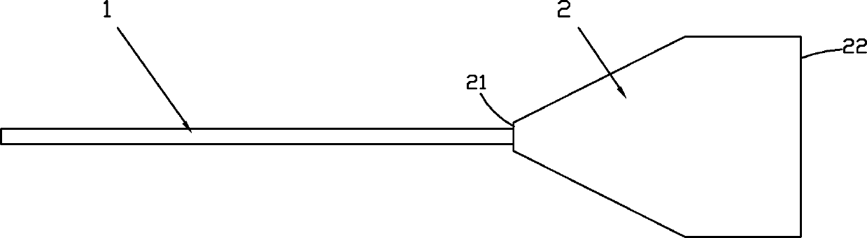
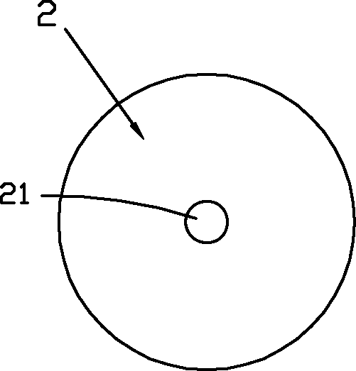
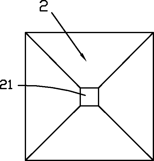
[0022] see Figure 1 ~ Figure 4 , the end face protection structure of the high-power laser fiber of the present invention, comprising: a high-power laser fiber 1 and a glass block 2 welded to one end of the high-power laser fiber 1; It is a cone structure, and the thin end 21 of the cone structure is welded to the optical fiber. The shape of the end surface of the thin end 21 can be circular, and can also be processed into a polygonal structure according to the process requirements.

[0023] Further, the cone angle of the cone structure of the glass block 2 is larger than the beam divergence angle of the laser output from the optical fiber.

[0024] The area of ​​the narrow end 21 of the glass block 2 is equal to or greater than the area of ​​the optical fiber. The thicker end 22 of the glass block is a cylinder or a prism.

[0025] The end surface of the thicker end 22 of the glass block 2 is coated with an anti-reflection film that can reduce the reflection loss of the en...


PUM


Abstract

The invention discloses an end face protection structure of a high-power laser optical fiber. The end face protection structure comprises the high-power laser optical fiber and a glass block which is fused with one end of the high-power laser optical fiber, wherein one end, which is fused with the high-power laser optical fiber, of the glass block is of a cone structure; the cone end face is of a circular or polygonal structure; and the area of the end face is equal to or greater than the area of the optical fiber. According to the end face protection structure, as one piece of conical glass block is fused with the high-power laser optical fiber, the damage to the optical fiber caused by the over-high laser power density generated on the output face of the laser is prevented ; the taper of the glass block is greater than the divergence angle of a light beam output by the optical fiber, so that all lights output by optical fiber are transmitted inside the glass block; the size of the fine end of the glass block is small, so that the difficulty for fusion of the glass block and the optical fiber is reduced; the size of the end face of a thick end of the glass block is larger, so that an anti-reflection film is conveniently plated, and the unnecessary energy loss is reduced; and the structure is extremely suitable for the output end of the high-power optical fiber laser and is also suitable for a coupling input end or output end of a high-power semiconductor laser coupled with the optical fiber.

Description

technical field [0001] The invention belongs to the field of laser devices, and in particular relates to an end face protection structure of a high-power laser optical fiber. Background technique [0002] Due to the special gain waveguide structure, the fiber laser has high gain and easy heat dissipation, and has its unique advantages in outputting high-power laser with high beam quality. At present, high-power fiber lasers are widely used in defense, industry and other fields, but due to The fiber core is too thin, and the laser power density transmitted in the fiber is extremely high, which makes the fiber end face prone to damage. This is an important problem in the development and application of high-power fiber lasers. [0003] At present, there are some protective measures that can increase the area of ​​the end face and achieve certain protection for the output end face. For example, one method is to fuse a section of extremely short optical fiber that is consistent w...

Claims


Application Information

Patent Timeline
Patent Type & Authority Applications(China)
IPC IPC(8): H01S3/067
Inventor 周军朱玲克里斯托弗·T·濑户王颖张博臻
Owner OPTTON
Why Eureka
Try Eureka