
Structure and cooling method of a motor stator core

A motor stator and stator iron core technology is applied to the structure and cooling of the motor stator iron core, the structure of the motor stator iron core, the cooling structure and cooling field of the motor stator, and can solve the problem that it cannot be directly blown to the stator iron core, and the stator winding cannot dissipate heat and reduce heat dissipation. Problems such as motor torque and power

Active Publication Date: 2016-02-03
曹宇轩
View PDF6 Cites 0 Cited by
  • Summary
  • Abstract
  • Description
  • Claims
  • Application Information

AI Technical Summary

Problems solved by technology

[0009] 1. The stator core is made of non-oriented silicon steel sheet, and its hysteresis loss and eddy current loss are relatively large, that is, the iron loss is relatively large;
[0010] 2. The open, semi-open or semi-closed slots of the stator will cause cogging, which will cause torque ripple, and when the motor rotates at a high speed, it will generate a large wind resistance loss and form a large wind noise;
[0011] 3. The method of stator skew or rotor skew can reduce the torque ripple caused by the cogging effect, but it also reduces the torque and power of the motor;
[0012] 4. For the stator core with traditional overall structure, the end of the motor winding is longer, which not only reduces the utilization rate of the wire, increases the copper consumption of the motor, but also increases the axial size of the motor;
[0013] 5. For traditional distributed stator windings, usually only multi-strand round enameled wires can be used, and it is difficult to use rectangular enameled wires, so the utilization rate (slot fullness rate) of the stator wire slot of the motor is low;
[0014] 6. In the existing medium and small motors, the iron core of the stator is an integral structure, and the forced air cooling of the stator can only be indirect. The cooling air is forced to blow to the end of the motor stator and the stator shell, and cannot be directly blown to the surface of the stator winding , and cannot be directly blown into the stator core;
[0015] 7. For the forced air cooling method that directly blows through the air gap, although the surface of the inner diameter of the stator core can be directly cooled, due to the shielding of the slot wedge, it is impossible to directly dissipate heat from the stator winding through convection, and the particulate matter that cannot be filtered out in the air It may enter the bearing from the end of the motor rotor, reduce the lubrication effect of the bearing lubrication system, increase the resistance of the bearing, and reduce the service life of the bearing;
[0023] 15. In the existing motors with segmented stator cores, the end baffles of the winding frame shield the windings in the slots, and cooling oil nozzles cannot be installed on the stator cores, so splash oil cooling cannot be used. , the cooling oil is directly sprayed onto the surface of the winding, and the cooling of the winding can only be cooled by indirect cooling, that is, the heat of the winding is transmitted to the teeth of the stator core, and then dissipated by the surface of the core;

Method used


Image

  • Structure and cooling method of a motor stator core
  • Structure and cooling method of a motor stator core
  • Structure and cooling method of a motor stator core

Examples


Embodiment 1

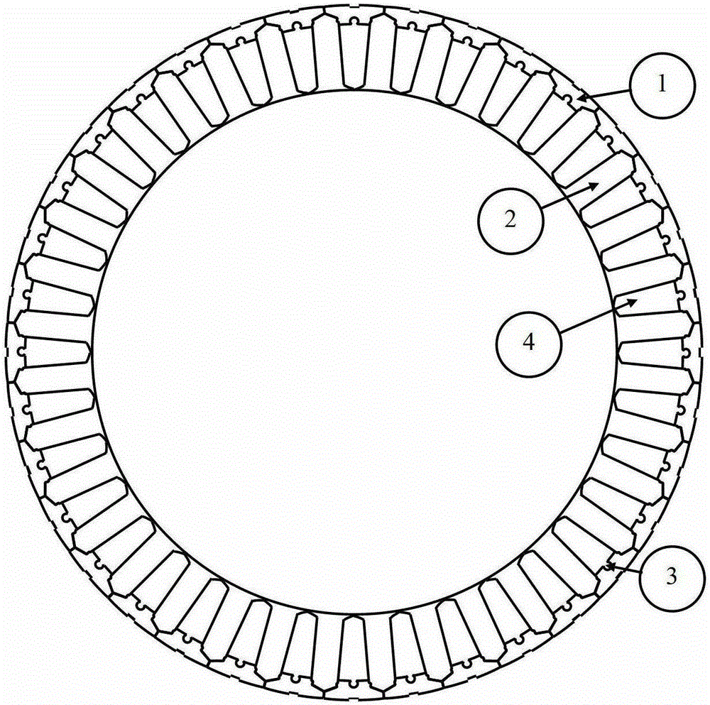
[0070] With reference to the accompanying drawings, the preferred embodiment of the present invention is a motor stator core structure that adopts a spliced ​​structure of oriented silicon steel sheets as shown in the accompanying drawings. The motor stator is a closed slot, so there is no cogging effect. Skeleton with oil guide grooves) concentrated winding structure, using jet splash oil cooling cooling method.

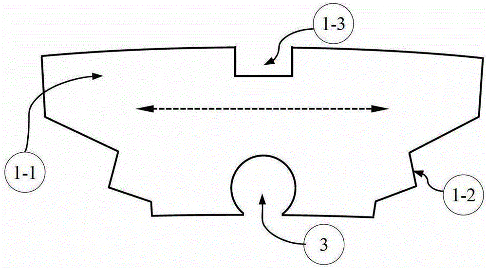
[0071] Specifically, in the motor stator core structure of the present invention, the stator core is divided into two basic structural components, one is the stator yoke unit 1 , and the other is the stator tooth unit 2 . The stator yoke unit 1 has the same number as the stator tooth unit 2, both equal to the number of slots Z of the stator 1 . In the stator yoke unit 1 proposed by the present invention, the orientation direction of the silicon steel sheet is the circumferential (tangential) direction, that is, the extension direction of the yoke, and on the stator...

Embodiment 2

[0076] The structure of the stator core of the motor is the same as that of Embodiment 1, and the difference from Embodiment 1 lies in the cooling method of forced air cooling.

Embodiment 3

[0078] The structure of the stator core of the motor is the same as that of Embodiment 1, and the difference from Embodiment 1 lies in the cooling method of water cooling.


PUM


Abstract

The invention relates to a structure of a motor stator core and a cooling method for a motor stator based on the structure of the motor stator core. The structure is characterized in that the stator core is formed by splicing and combining stator yoke units and stator tooth units, wherein the quantities of the stator yoke units and the stator tooth units are the same, and are equal to the slot number Z1 of a stator; the stator yoke units and the stator tooth units are formed by laminating oriented silicon steel sheets; a stator yoke unit is connected between every two adjacent tooth units; the tooth units and the stator yoke units are in joggle joint; the silicon steel sheets of the stator yoke units are oriented circumferentially; and the silicon steel sheets of the stator tooth units are oriented radially. The cooling method is selected from one of air cooling, water cooling and oil cooling. The structure has the advantage that the motor has the characteristics of low ferromagnetic loss, high efficiency, low torque pulsation, low slot effect, low running noise, low wind resistance, high slot fullness rate of a stator winding, high utilization ratio of a silicon steel sheet material, suitability of the stator for automatic mass production and the like.

Description

technical field [0001] The invention relates to a structure and a cooling method of a stator core of a motor, in particular to a structure of a stator core of a motor using oriented silicon steel sheets, and a cooling structure and a cooling method of a motor stator using the core of this structure, belonging to the technical field of motors . Background technique [0002] Rotating electrical machines (including electric motors and generators) are widely used in different fields such as modern industry, agriculture, transportation, national defense, science and technology, and daily life. Typically, a rotating electrical machine includes components such as a stator and a rotor, and the stator and rotor of the motor usually include an iron core, which is used to form a magnetic circuit, guide the flow of magnetic flux reasonably, generate electromagnetic force and output torque. The magnetic flux of the motor is generated by the current in the motor windings and the permanen...

Claims


Application Information

Patent Timeline
Patent Type & Authority Patents(China)
IPC IPC(8): H02K1/16H02K1/20H02K9/04H02K9/19H02K9/20H02K3/34
Inventor 曹宇轩
Owner 曹宇轩
Learn More