Nano-material transfer deposition method
A technology of nanomaterials and deposition methods, applied in the field of assembly and manufacturing of micro-nanostructures, can solve the problems of introducing impurities, optimizing the electrical and mechanical properties of nanomaterials, etc.
- Summary
- Abstract
- Description
- Claims
- Application Information
AI Technical Summary
Problems solved by technology
Method used
Image
Examples
Embodiment 1
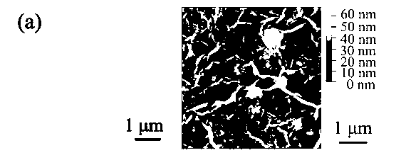
[0035] In this example, a graphene oxide film will be deposited on a flat silicon substrate. The specific process is as follows:
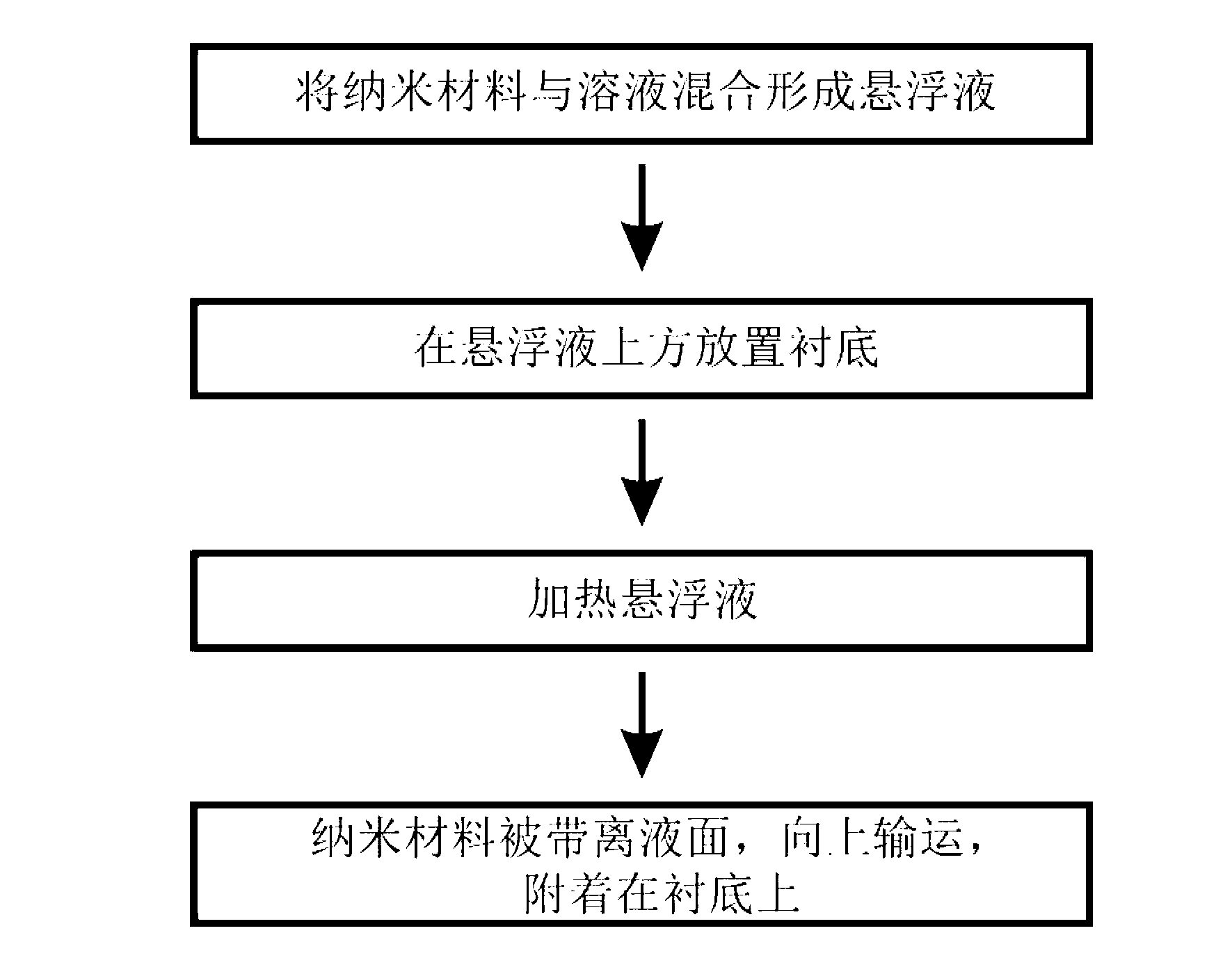
[0036] 1) Mix flake graphene oxide with high-purity water at a ratio of 1 mg / mL, put it into an ultrasonic machine and oscillate and disperse for 5 hours to form a graphene oxide suspension;
[0037] 2) Turn on the power of the oil bath heating pot to keep it at a constant temperature of 100°C;
[0038] 3) the glass container that the graphene oxide suspension is housed is placed in an oil bath and heated at a constant temperature of 100°C;
[0039] 4) Select a 1cm×1cm (100) single crystal silicon wafer with a flat surface as the substrate;
[0040] 5) Fix the substrate on the plastic support, put the substrate together with the plastic support into the graphene oxide suspension, make the front of the substrate face the liquid surface of the suspension, and the angle between the substrate surface and the liquid surface is 0° , the distance betwe...
Embodiment 2
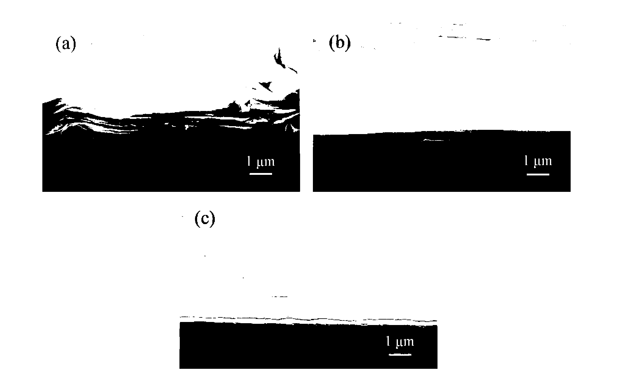
[0044] In this example, graphene oxide films will be deposited for different times on a flat silicon substrate, and their thicknesses will be characterized. The specific process is as follows:
[0045] 1) Mix flake graphene oxide with high-purity water at a ratio of 1 mg / mL, put it into an ultrasonic machine and oscillate and disperse for 5 hours to form a graphene oxide suspension;
[0046] 2) Turn on the power of the oil bath heating pot to keep it at a constant temperature of 100°C;
[0047] 3) the glass container that the graphene oxide suspension is housed is placed in an oil bath and heated at a constant temperature of 100°C;
[0048] 4) Select a 1cm×1cm (100) single crystal silicon wafer with a flat surface as the substrate;
[0049] 5) Put the substrate on a plastic support, put the substrate together with the plastic support into the graphene oxide suspension, make the front of the substrate face the liquid surface of the suspension, and the angle between the substrat...
Embodiment 3
[0053] In this embodiment, the graphene oxide film 2 will be deposited on the concave-convex groove-shaped microstructure array 1 of the silicon wafer, such as Figure 4 shown. The pitch and width of the concave-convex groove-like microstructure are 20 μm, and the length is 2 mm. The specific process is as follows:
[0054] 1) Prepare a concave-convex groove-shaped microstructure array 1 on a 1cm×1cm n-type silicon wafer;
[0055] 2) Mix flake graphene oxide with high-purity water at a ratio of 1 mg / mL, put it into an ultrasonic machine and oscillate and disperse for 5 hours to form a graphene oxide suspension;
[0056] 3) Turn on the power of the oil bath heating pot to keep it at a constant temperature of 100°C;
[0057] 4) the glass container that the graphene oxide suspension is housed is placed in an oil bath and heated at a constant temperature of 100°C;
[0058] 5) Select the concave-convex groove-shaped microstructure array 1 obtained in step 1) as the substrate; ...
PUM
| Property | Measurement | Unit |
|---|---|---|
| length | aaaaa | aaaaa |
| height | aaaaa | aaaaa |
| surface roughness | aaaaa | aaaaa |
Abstract
Description
Claims
Application Information
 - R&D
- Intellectual Property
- Life Sciences
- Materials
- Tech Scout
- Unparalleled Data Quality
- Higher Quality Content
- 60% Fewer Hallucinations
Browse by: Latest US Patents, China's latest patents, Technical Efficacy Thesaurus, Application Domain, Technology Topic, Popular Technical Reports.
© 2025 PatSnap. All rights reserved.Legal|Privacy policy|Modern Slavery Act Transparency Statement|Sitemap|About US| Contact US: help@patsnap.com


