Preparation method of large-power high-magnification lithium iron phosphate battery

A lithium iron phosphate battery, lithium iron phosphate technology, applied in the manufacture of electrolyte batteries, battery electrodes, non-aqueous electrolyte batteries, etc., to achieve improved conductivity or lithium ion migration speed, conductive ion or lithium ion migration speed, safety and reliability. The effect of high rate performance improvement

Inactive Publication Date: 2013-09-11
宜兴奕润新能源科技有限公司
View PDF5 Cites 13 Cited by
  • Summary
  • Abstract
  • Description
  • Claims
  • Application Information

AI Technical Summary

Problems solved by technology

[0004] The technical problem to be solved by the present invention is to provide a brand-new preparation method of lithium iron phosphate battery that can be used under high-rate conditions, which solv

Method used


Image

  • Preparation method of large-power high-magnification lithium iron phosphate battery
  • Preparation method of large-power high-magnification lithium iron phosphate battery
  • Preparation method of large-power high-magnification lithium iron phosphate battery

Examples


Embodiment 1

[0026] 1) Prepare the positive electrode sheet.

[0027] 1.1) Preparation of modified lithium iron phosphate cathode material: 6.5kg of isopropanol, 0.8kg of glucose, Nb 2 o 5 0.01kg, 1.290kg of ammonium dihydrogen phosphate, 1.905kg of ferrous oxalate, and 0.22kg of lithium carbonate were successively put into a ball mill (the theoretical molar content of Nb in the proportioning ratio was 1%), ball milled for 3 hours, and then put into a sand mill to sand Grind for 3 hours, then pass through a double-cone vacuum dryer in Dry at high temperature for 5 hours to obtain the precursor, and the precursor is passed through under the protection of nitrogen. keep warm for 4 hours, Heat preservation for 10 hours, and then natural cooling to obtain a lithium iron phosphate material, and finally crushed by a pulverizer to obtain a modified lithium iron phosphate positive electrode material. The tested Nb molar content is 0.99%, and the specific surface area is 13.2m2 / g.

[0028] 1...

Embodiment 2

[0038] 2) Prepare the positive electrode sheet.

[0039] 1.1) Preparation of modified lithium iron phosphate cathode material: Put 6.5kg of isopropanol, 0.8kg of glucose, 0.006kg of cobalt oxide, 1.290kg of ammonium dihydrogen phosphate, 1.905kg of ferrous oxalate, and 0.22kg of lithium carbonate into a ball mill in sequence (theoretical molar content of Co is 1% in the proportioning), ball milled for 3 hours, then put into the sand mill for sand milling for 3 hours, then passed through the double cone vacuum drier Dry at high temperature for 5 hours to obtain the precursor, and the precursor is passed through under the protection of nitrogen. keep warm for 4 hours, Heat preservation for 10 hours, and then natural cooling to obtain a lithium iron phosphate material, and finally crushed by a pulverizer to obtain a modified lithium iron phosphate positive electrode material. The tested Co molar content is 0.98%, and the specific surface area is 12.5m2 / g.

[0040] 1.2) The a...


PUM

PropertyMeasurementUnit
Specific surface areaaaaaaaaaaa
Diameteraaaaaaaaaa
Thicknessaaaaaaaaaa

Abstract

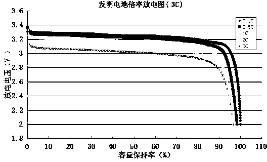
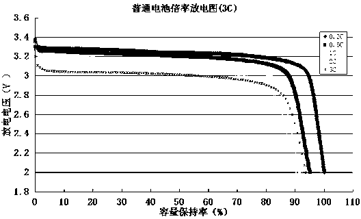
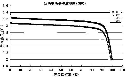
The invention discloses a preparation method of a large-power high-magnification lithium iron phosphate battery. The method is characterized in that a modified lithium iron phosphate material, a conductive agent, an adhesive and a dispersing agent are used for preparing a positive plate; then, a conductive agent, a negative active substance, an adhesive, a thickening agent and a modified lithium iron phosphate material are used for preparing a negative plate; finally, the positive plate, the negative plate, a diaphragm and electrolyte are made into a soft battery through the steps of lamination, injection and assembling, and the soft battery is subjected to formation and capacity grading to obtain the large-power high-magnification lithium iron phosphate battery. By improving the conductivity of the positive plate and the negative plate, the high-magnification discharging capacity of the battery can be improved, the large power needed by a new energy car for high-speed driving, climbing, starting and rapid charging can be achieved, and the application range of the lithium-ion battery can be enlarged.

Description

technical field [0001] The invention relates to the field of lithium ion batteries, in particular to a method for preparing a high-power and high-rate lithium iron phosphate battery. Background technique [0002] In the current situation of serious environmental pollution and energy shortage, the development of new materials and renewable energy technologies has become one of the major issues to be solved by human beings in the 21st century. The chemical power source as an energy storage and conversion device is an important means of effectively utilizing energy. At present, lithium-ion batteries and fuel cells are research hotspots in the field of chemical power sources, especially as power batteries, which are of great significance to environmental protection and social development. Lithium-ion batteries, in particular, have attracted widespread attention from all over the world because of their advantages such as high operating voltage, high energy density, low self-disch...

Claims


Application Information

Patent Timeline
IPC IPC(8): H01M10/058H01M4/58H01M4/62
CPCY02E60/10Y02P70/50
Inventor 徐建平蒋美娣徐勇
Owner 宜兴奕润新能源科技有限公司
Why Eureka
Try Eureka