Omni-directional acceleration sensor device of optical fibers of cantilever

A technology of acceleration sensor and cantilever beam, which is applied in the direction of acceleration measurement by using inertial force, can solve the problems of insufficient working frequency band of undamped sensor, measurement acceleration amplitude range, and inability to detect speed direction, etc., to expand the working frequency band and accuracy High, light weight effect

Active Publication Date: 2013-09-25
南通中选智科环境科技有限公司
View PDF9 Cites 4 Cited by
  • Summary
  • Abstract
  • Description
  • Claims
  • Application Information

AI Technical Summary

Problems solved by technology

[0013] The purpose of the present invention is to solve the problems of insufficient working frequency band of the undamped sensor and the inability to detect the direction of the velocity, the limited range of the measured acceleration amplitude due to the small end face and the difficulty of alignment.

Method used


Image

  • Omni-directional acceleration sensor device of optical fibers of cantilever
  • Omni-directional acceleration sensor device of optical fibers of cantilever
  • Omni-directional acceleration sensor device of optical fibers of cantilever

Examples


Embodiment 1

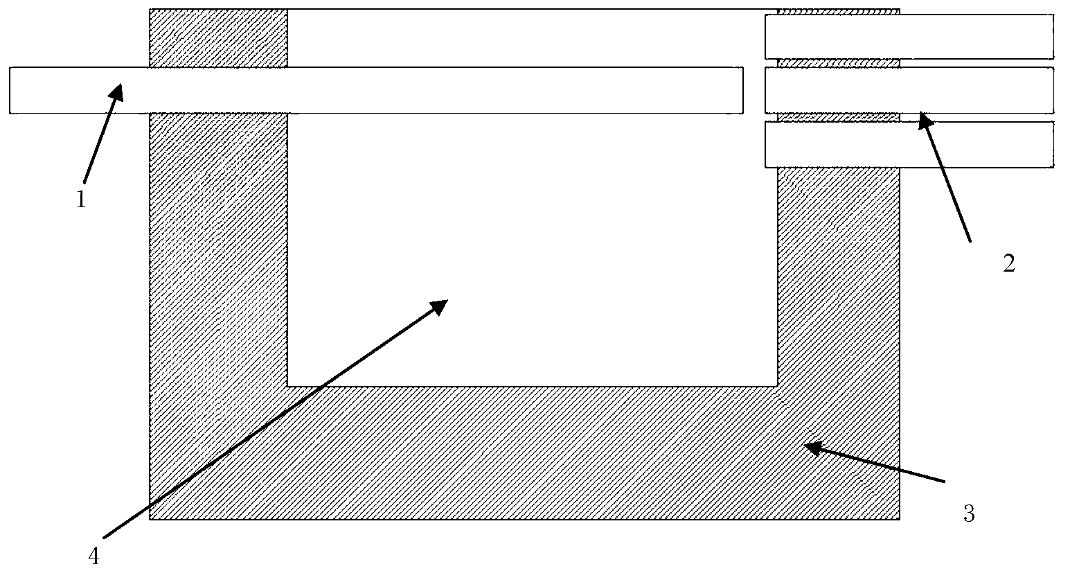
[0104] The rectangular airtight casing used in the present invention is made by injection molding. First use clay to make a shell mold, and then use thermoplastic plastics, such as polyethylene plastics and polyvinyl chloride plastics, to heat and inject them. In the process of making injection molds, attention should be paid to the production of pouring system, guiding system and molding system. The core-pulling system and ejection system can be omitted, and the heat dissipation system can be simplified into multiple small exhaust holes. When the plastic is cooled and solidified, take it out, and carry out shaping, grinding and polishing. After forming, use Tamiya Fine Pin Vise-(0.1~3.2mm) precision hand drill to drill holes.

Embodiment 2

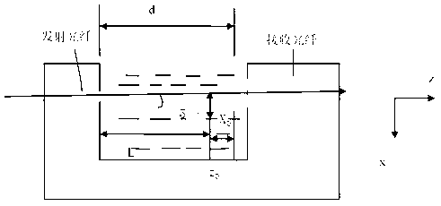
[0106] The transmitting optical fiber and the receiving optical fiber bundle in the present invention use plastic optical fibers with a diameter of 0.25 to 3mm, and utilize the larger numerical aperture of the plastic optical fiber to be more easily coupled with the light source, and the toughness of the plastic optical fiber is not easy to be broken. The larger fiber diameter makes it easier to align the launch fiber with the main receive fiber. When selecting the diameter of the plastic optical fiber, the influence of the use environment should be fully considered. An excessively large optical fiber diameter will result in reduced sensitivity, while an excessively small optical fiber will complicate the processing process.

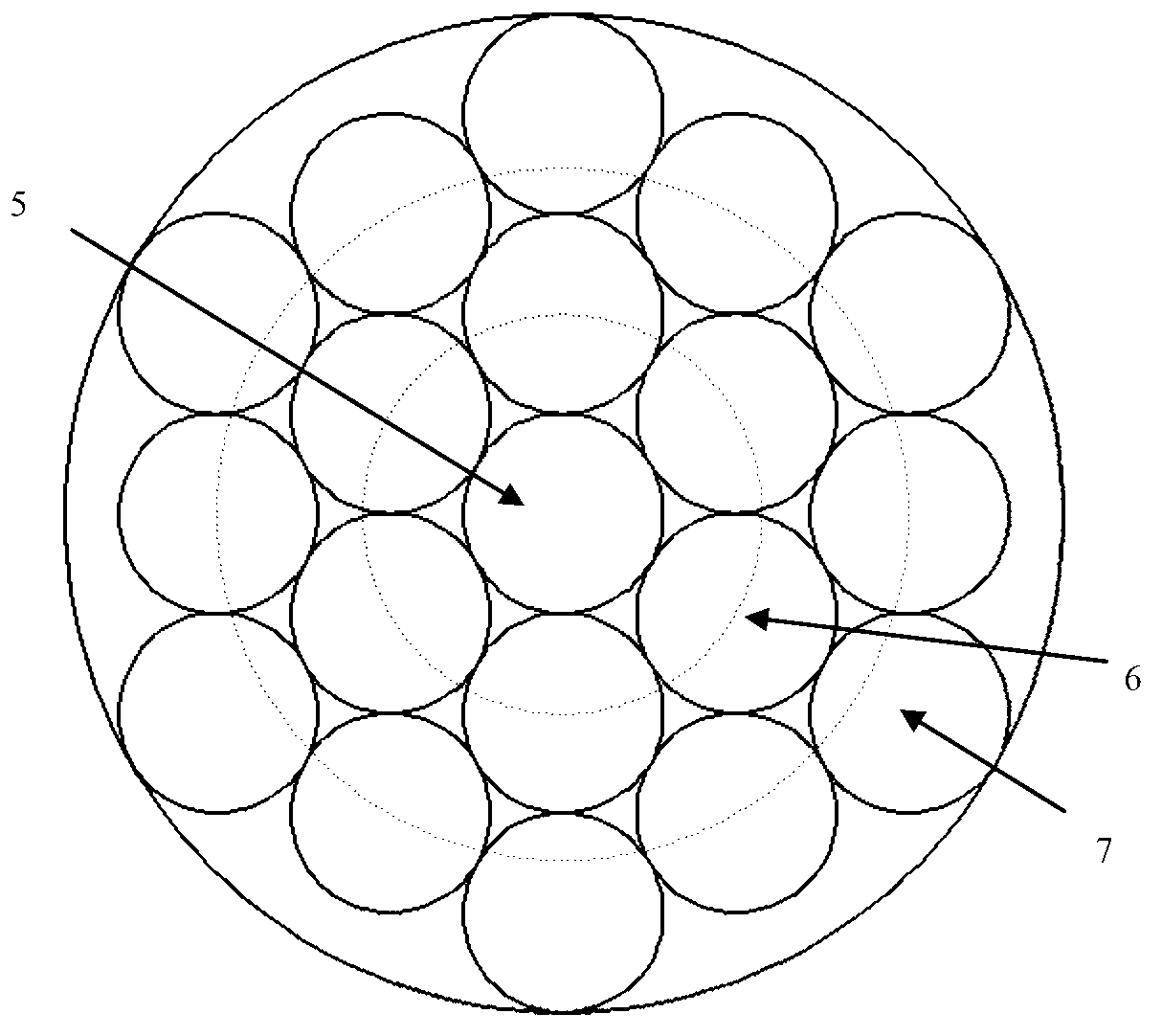
[0107] In the process of making optical fiber bundles, it should be selected with excellent light transmittance, high bonding strength, high refractive index, good environmental performance, good weather resistance, and can be dispensed by a glue dispense...


PUM


Abstract

An acceleration sensor device of optical fibers of a cantilever based on intensity modulation method detection structurally comprises a transmission optical fiber (1), a receiving optical fiber bundle (2) and a rectangular sealed shell body (3), wherein a transmission plastic optical fiber interface (4) and a receiving plastic optical fiber interface (5) are formed in the center of the left end surface and in the center of the right end surface of the rectangular sealed shell body (3) respectively, and the shell body (3) is filled with transparent liquid (7) to counteract the gravity influence. The receiving optical fiber bundle (2) is an optical fiber bundle arranged in a cellular mode and formed by a plurality of plastic optical fibers, a main receiving optical fiber is located in the center, six optical fibers surround the main optical fiber to form a first layer structure, and twelve optical fibers surround the first layer to form a second layer of detection structure. When a system applies acceleration, the cantilever deviates from the main receiving optical fiber, the deviation direction is the acceleration direction, and the acceleration and the acceleration direction can be obtained by calculating the light intensity difference between the main receiving optical fiber and the surrounding receiving optical fibers.

Description

technical field [0001] The invention relates to a novel omnidirectional cantilever beam fiber optic acceleration sensor structure and its working field, in particular to the field of measurable motion acceleration and oscillation phase. Background technique [0002] Acceleration sensor is an important sensor commonly used for shock and vibration measurement in many fields such as industry and national defense. A conventional accelerometer is an electronic device capable of measuring acceleration forces. The acceleration force is the force acting on the object when the object is accelerating, just like the gravity of the earth, that is, gravity. The acceleration force can be a constant, such as g, or it can be a variable. Traditional acceleration sensors can be divided into piezoelectric acceleration sensors, piezoresistive acceleration sensors, capacitive acceleration sensors, capacitive acceleration sensors and servo acceleration sensors according to the different princip...

Claims


Application Information

Patent Timeline
Patent Type & Authority Applications(China)
IPC IPC(8): G01P15/03
Inventor 陆云清陈陶呼斯楞
Owner 南通中选智科环境科技有限公司
Why Eureka
Try Eureka