
Intelligent electrical valve locator main board hardware circuit

A valve positioner and hardware circuit technology, applied in instruments, valve details, valve devices, etc., can solve the problems of high price of intelligent electric positioner and long purchase cycle, achieve good suppression effect, improve interference, and suppress high frequency the effect of interference

Inactive Publication Date: 2013-10-09
TIANJIN JINGTONG CONTROL INSTR TECH
View PDF3 Cites 10 Cited by
  • Summary
  • Abstract
  • Description
  • Claims
  • Application Information

AI Technical Summary

Problems solved by technology

At present, most of the intelligent valve positioners commonly used in the domestic market are some large foreign companies, such as Siemens, Fisher, ABB, etc. The domestic electric valve positioners use the traditional mechanical force balance principle, there are some Insufficient and unable to meet the needs of process control development, while the intelligent electrical positioner imported from abroad is expensive and has a long purchase cycle, which is far from meeting the needs of the domestic market for low cost, high intelligence, and high progress. It is urgent to develop a Low-cost, high-quality, high-intelligence, high-speed intelligent electrical valve positioner, so it is necessary to research and design intelligent electrical valve positioner

Method used


Image

  • Intelligent electrical valve locator main board hardware circuit
  • Intelligent electrical valve locator main board hardware circuit
  • Intelligent electrical valve locator main board hardware circuit

Examples


Embodiment Construction

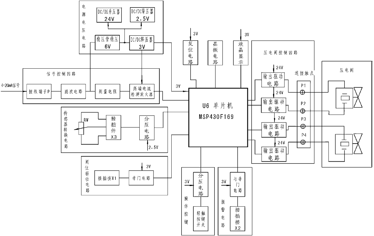
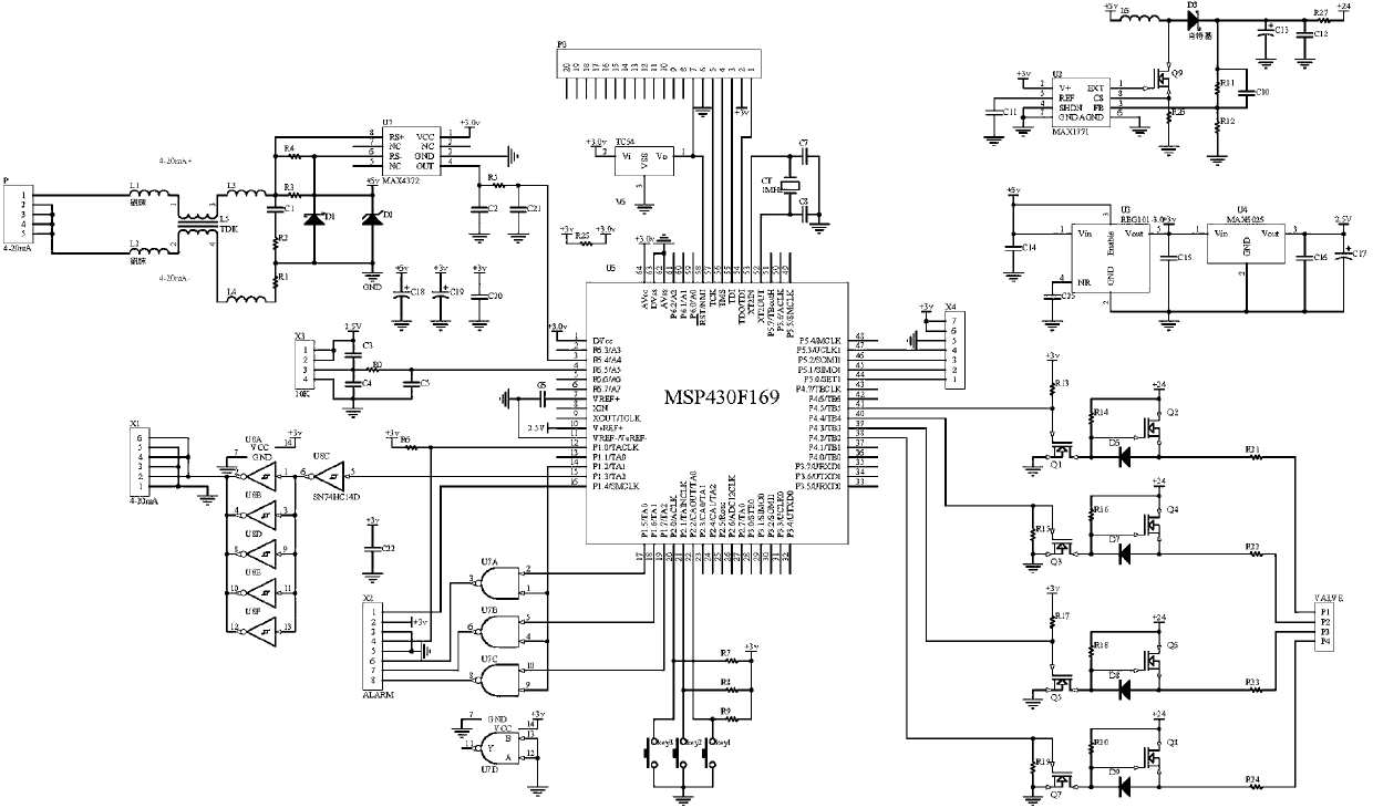
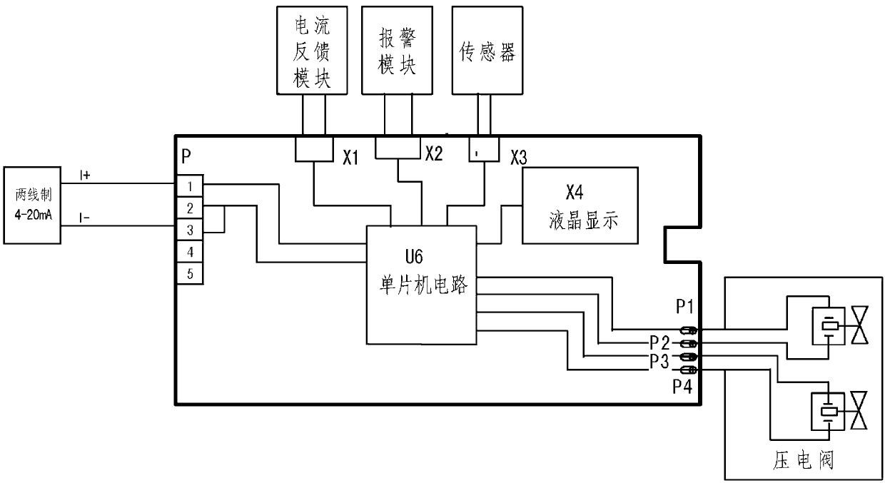
[0029] Such as figure 1 As shown, a hardware circuit of the motherboard of an intelligent electric valve positioner includes a signal control circuit, a sensor conversion circuit, a single-chip microcomputer circuit, a piezoelectric valve control circuit, a power supply voltage circuit, a liquid crystal display circuit, an operation key circuit, an alarm circuit, and a valve position drive Circuit (for current feedback), the signal control loop consists of terminal P, filter circuit, measuring resistor, and high-end current detection amplifier. The sensor conversion circuit consists of a connector X3 and a voltage divider circuit. The single-chip microcomputer circuit includes a single-chip microcomputer, a crystal oscillator circuit, and a reset circuit. The piezoelectric valve control circuit consists of four output drive circuits and connecting contacts. The power supply voltage circuit includes a voltage regulator tube voltage regulator circuit, a DC / DC boost converter, ...


PUM


Abstract

The invention relates to an intelligent electrical valve locator main board hardware circuit. A single chip microcomputer circuit is connected with a signal control circuit, a sensor switching circuit, a piezoelectric valve control circuit, a liquid crystal display circuit, an operation keying circuit, an alarm circuit and a valve location drive circuit, and a supply voltage circuit provides working voltages for the signal control circuit, the sensor switching circuit, the single chip microcomputer circuit, the piezoelectric valve control circuit, the liquid crystal display circuit, the operation keying circuit, the alarm circuit and the valve location drive circuit respectively. The intelligent electrical valve locator main board hardware circuit has the advantages that by collecting a two-wire system 4-20mA signal of set valve opening and a fed-back practical valve opening signal of the set valve opening from a regulator, the circuit outputs corresponding control signals to control opening and closing of a piezoelectric valve through blurring operation and decision making after the deviation and the deviation change rate of the two signals are calculated through a single chip microcomputer, therefore, the amount of air entering an adjusting valve air chamber is controlled, a valve element is pushed to move and accurately located, and the aim of automatically adjusting an adjusting valve is achieved.

Description

technical field [0001] The invention relates to a control circuit, in particular to a main board hardware circuit of an intelligent electric valve positioner. Background technique [0002] The automatic control of the production process is referred to as process control, which occupies an extremely important position in industrial production. Process control has developed from an analog control system to an analog-digital mixed distributed control system, and further developed to a fieldbus control system. The quality of process control depends largely on process control instruments, including transmitters, regulators, actuators and various auxiliary devices. Pneumatic control valve is a very important actuator in process control, and valve positioner, as one of the main accessories of pneumatic control valve, can improve valve characteristics, improve control accuracy, speed and increase control flexibility. The development of valve positioners towards intelligent and fie...

Claims


Application Information

Patent Timeline
IPC IPC(8): F16K31/02G05B19/042
Inventor 白春娥
Owner TIANJIN JINGTONG CONTROL INSTR TECH
Learn More