
High-production-efficiency laser linear light source assembly and assembly method thereof

A technology of laser line light source and assembly method, which is applied in the direction of optical components, light source fixing, optics, etc., can solve the problems of low production efficiency, high processing cost, and difficult debugging, and achieve high production efficiency, low production cost, and difficult debugging small effect

Inactive Publication Date: 2015-05-20
中山市天志光电科技有限公司
View PDF4 Cites 0 Cited by
  • Summary
  • Abstract
  • Description
  • Claims
  • Application Information

AI Technical Summary

Problems solved by technology

[0006] The weak point of the marking instrument in the above-mentioned prior art is: (1) the special structure and the assembling and debugging mode of the described hollow cylinder 5 make it necessary to adopt aluminum material with better toughness to be machined Hard, relatively brittle cast aluminum realizes this structure by one-time casting molding), the processing cost is higher, and the production efficiency is lower; (2) adopt four screws to adjust the central axis of the cylindrical lens 1 and the laser generating The included angle of the laser beam output by the component is difficult to debug; (3) After the assembly and debugging are completed, there is mechanical stress at the connecting block 7 of the laser head component, which causes the above-mentioned existing laser line light source to be in use. Part 6 is prone to loosening or metal deformation, which leads to a non-right angle between the central axis of the cylindrical lens 1 and the output laser beam of the laser generating assembly, which in turn causes the laser line output by the laser line light source to appear arc-shaped ,Affect

Method used


Image

  • High-production-efficiency laser linear light source assembly and assembly method thereof
  • High-production-efficiency laser linear light source assembly and assembly method thereof
  • High-production-efficiency laser linear light source assembly and assembly method thereof

Examples


Embodiment 1

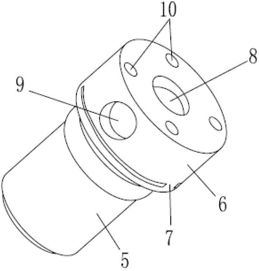
[0027] See Figure 4-5 , the body of the laser line light source assembly of the present embodiment includes: a body, the body includes: a hollow cylindrical main body 5 and a laser generating assembly 13 arranged in the main body 5; There is a radially penetrating assembly groove 11, which is provided with a radially distributed cylindrical lens 1; the bottom surface of the assembly groove 11 is provided with a pair of radially symmetrically distributed and oppositely arranged inclined surfaces 12; by adjusting The position of the cylindrical lens 1 on the pair of inclined surfaces 12 is used to fine-tune the angle between the central axis of the cylindrical lens 1 and the laser beam output by the laser generating assembly 13; when the angle is a right angle, Both ends of the cylindrical lens 1 are fixed with glue.

[0028] As an optimal embodiment, the inclined surface 12 is an arc-shaped inclined surface matched with the end of the cylindrical lens 1, so that the contact b...

Embodiment 2

[0033] The assembly method of the laser line light source assembly in the above-mentioned embodiment 1 includes the following steps:

[0034] A. Fix the laser generating assembly 13 in the main body 5, and make the laser beam output by the laser generating assembly 13 suitable for passing through the central through hole 15;

[0035] B. The cylindrical lens 1 is arranged radially on the pair of inclined surfaces 12 in the fitting groove 11;

[0036] C, fix the elastic reed 14 on the top surface of the top end portion 6, to compress the cylindrical lens 1;

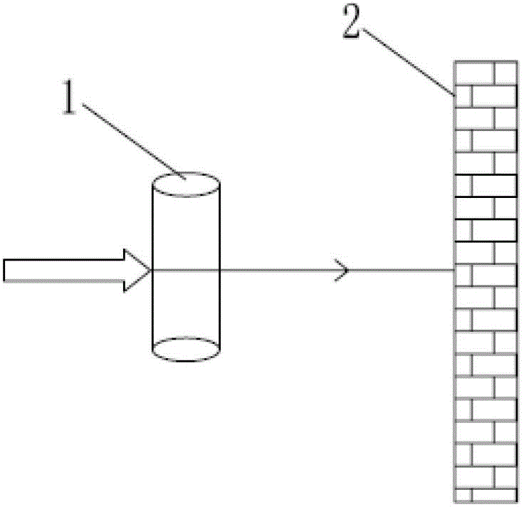
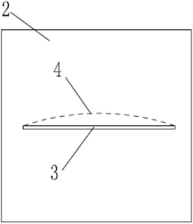
[0037] D. Fix the laser head assembly 13 on a debugging frame, and make the laser head assembly face a wall; a pair of screws are arranged on the debugging frame, and the pair of screws are oppositely arranged at the left and right ends of the cylindrical lens 1 , and is adapted to adjust the left and right positions of the cylindrical lens 1 on the pair of inclined surfaces 12 by synchronously rotating the pair of screws;...


PUM


Abstract

The invention relates to a laser linear light source assembly and an assembly method thereof. The center of the top end of a main body of a laser head assembly is provided with a radially-penetrative assembly groove, and a cylindrical lens is radially distributed in the assembly groove; the bottom surface of the assembly groove is symmetrically provided with a slope; the included angle between the central axis of the lens and the laser beam output by the laser generation assembly is finely adjusted by adjusting the position of the cylindrical lens on the slope; and when the included angle is a right angle, both ends of the cylindrical lens are fixed by glue. Compared with the four-screw adjustment method, the invention has the characteristics of simple structure, higher adjustment precision, convenient and visual adjustment, low adjustment difficulty, fewer working hours and the like. The main body of the assembly is suitable for cast aluminum one-step pressure casting; and compared with the machining mode, the cast aluminum one-step pressure casting has the characteristics of low production cost, high production efficiency, high precision, controllable product quality and the like. After the cylindrical lens is fixed by the glue, almost no mechanical stress exists, and thus, the reliability of the product is higher.

Description

[0001] This application is a divisional application, the patent application number of the original application: 201110361215.2, the name of the invention: laser line light source assembly and its assembly method, and the application date: 2011-11-17. technical field [0002] The invention relates to a laser line light source assembly and an assembly method thereof. Background technique [0003] The laser line projector is a laser emitting instrument that can obtain horizontal planes, vertical planes, horizontal lines, and vertical lines through laser beams in construction and interior and exterior decoration operations. One of the core technologies is high quality and high reliability. Laser line light source components. In addition to the use of laser line projectors, laser line light source components are also widely used in the cutting instructions of various plates such as steel and wood; the location indication of various equipment in the textile industry; the light cur...

Claims


Application Information

Patent Timeline
Patent Type & Authority Patents(China)
IPC IPC(8): G01C15/00G02B7/02F21V14/06F21V17/16
Inventor 李长丰吴秀兰戴志军樊莉
Owner 中山市天志光电科技有限公司
Features
  • Generate Ideas
  • Intellectual Property
  • Life Sciences
  • Materials
  • Tech Scout
  • Unparalleled Data Quality
  • Higher Quality Content
  • 60% Fewer Hallucinations
Learn More