Gas detection device and method

A gas detection and gas technology, which is applied in the field of gas detection devices with different ranges, can solve the problems of low light intensity of the sensor, low signal-to-noise ratio of the instrument, difficult measurement, etc., and achieve high measurement accuracy, good maintainability and simple structure. Effect

Active Publication Date: 2013-10-09
FOCUSED PHOTONICS
View PDF6 Cites 2 Cited by
  • Summary
  • Abstract
  • Description
  • Claims
  • Application Information

AI Technical Summary

Problems solved by technology

[0002] At present, in gas detection, there is a need to detect various gases, such as CO and CO2 in flue gas detection. The range of CO is 0-3000ppm, while the range of CO2 is 0-15%. There is a big difference between the two ranges , the traditional gas-phase filter non-dispersive infrared spectroscopy technology is difficult to realize the measurement of multi-component gases with different ranges. To achieve this, it is necessary to configure an infrared filter with a very narrow bandwidth
[0003] This type of analysis technology mainly has the following disadvantages: narrow-band infrared filters are usually very expensive and costly; after the light source beam passes through the narrow-band infrared filter, the light intensity attenuation is relatively large, resulting in low light intensity detected by the sensor, and the instrument signal Lower noise ratio, worse detection limit

Method used


Image

  • Gas detection device and method
  • Gas detection device and method
  • Gas detection device and method

Examples


Embodiment 1

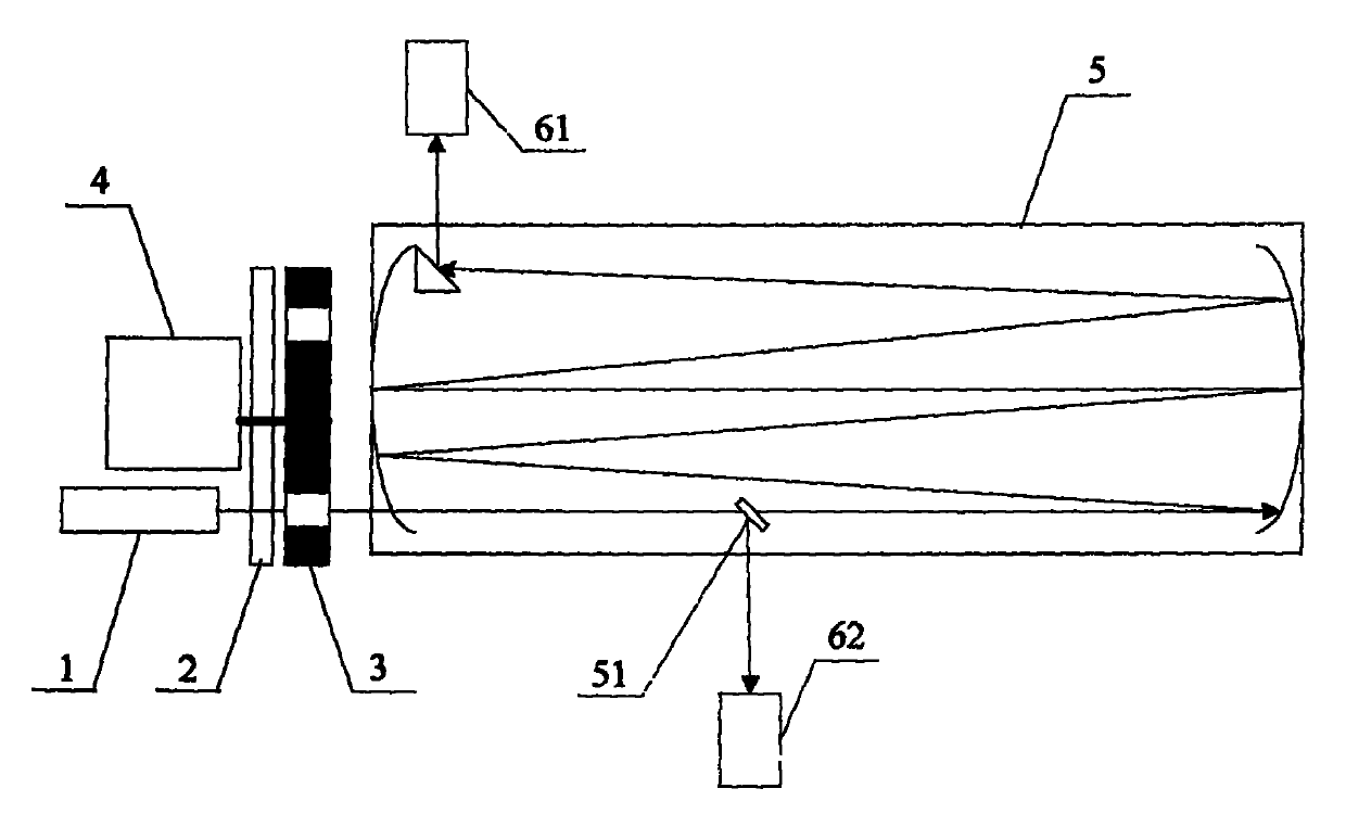
[0036] figure 1 A schematic diagram of the structure of the gas detection device according to the embodiment of the present invention is given schematically, such as figure 1 As shown, the gas detection device includes:

[0037] The infrared light source 1 , the chopper 2 and the GFC wheel 3 driven by the motor 4 , the White cavity 5 and the first sensor 61 are all existing technologies in the field of non-dispersive infrared spectroscopy, and will not be repeated here.

[0038] A spectroscopic component 51, the spectroscopic component 51 is arranged in the White cavity, and is used to separate the part of the measurement light emitted by the light source 1 and incident into the White cavity 5; preferably, the light splitting component is a light splitting component A mirror or a small hole with an aperture smaller than the light spot or an optical fiber bundle or an antireflection coating on the white cavity mirror arranged on the White cavity mirror.

[0039] figure 2 A ...

Embodiment 2

[0052] An application example of the gas detection device and method according to Embodiment 1 of the present invention in flue gas monitoring. It is specifically used to detect the content of carbon monoxide and carbon dioxide in the flue gas, wherein the concentration of carbon dioxide is high and the concentration of carbon monoxide is low.

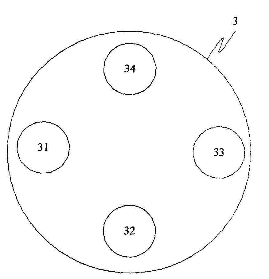
[0053] In this application example, the light source adopts an igniter, and the light splitting component adopts a reflector. A part of the measurement light entering the White cavity is reflected by the reflector and enters the second sensor, and the other part passes through the reflector. The second cavity and the fourth cavity are filled with nitrogen gas as zero gas. The first cavity is filled with 55% carbon monoxide, and the third cavity is filled with 60% carbon dioxide. One side of the first cavity and the second cavity adjacent to the light source is fixed with a filter that can pass the measurement light with the wavelength...

Embodiment 3

[0055] An application example of the gas detection device and method according to Embodiment 1 of the present invention in flue gas monitoring. It is specifically used to detect the content of carbon monoxide and carbon dioxide in the flue gas, wherein the concentration of carbon dioxide is high and the concentration of carbon monoxide is low.

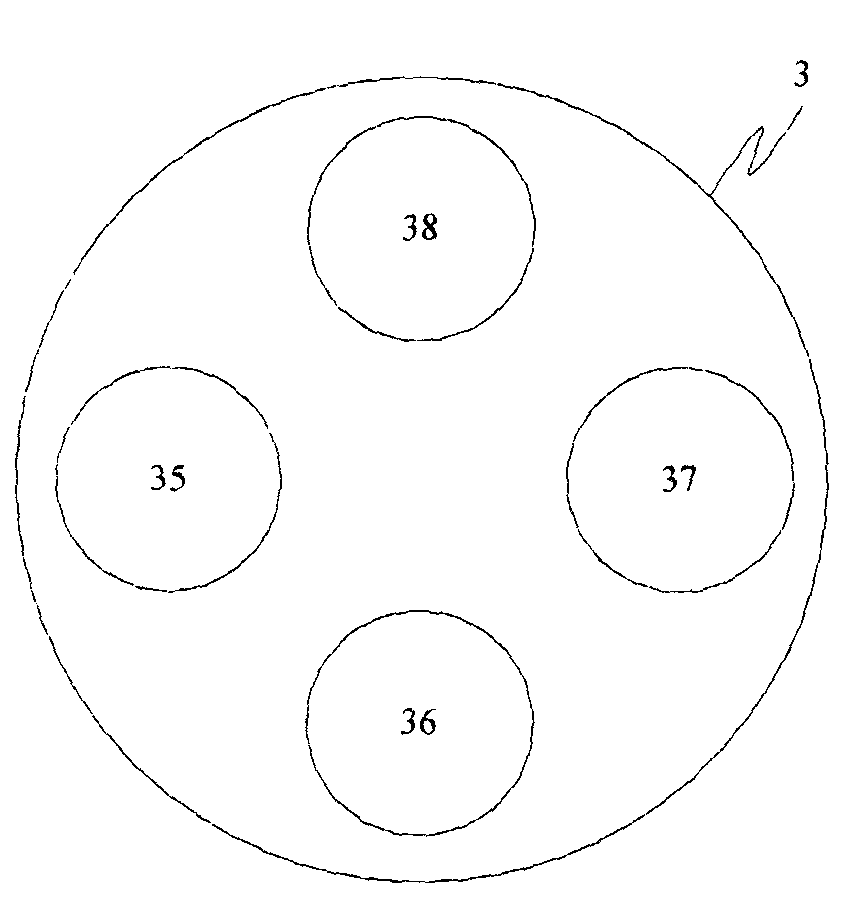
[0056] In this application example, a nickel alloy filament is used as the light source, and a small hole is used for the light-splitting component. Specifically, the aperture of the cavity mirror in the White cavity is smaller than that of the light spot, so that part of the light passes through the small hole and is emitted by the second sensor. take over. The second cavity and the fourth cavity are filled with nitrogen gas as zero gas. The first cavity is filled with 55% carbon monoxide, and the third cavity is filled with 60% carbon dioxide. The side of the first cavity and the second cavity close to the light source is fixed wit...


PUM


Abstract

The invention provides a gas detection device. The gas detection device comprises a light source, a GFC wheel, a White cavity and a first sensor, wherein a light splitting part is arranged in the White cavity and is used for separating out one part, emitted into the White cavity, of the light source; the GFC wheel is provided with a first cavity, a second cavity, a third cavity and a fourth cavity which are isolated mutually; an optical filter group is arranged on a measuring light path at one side, close to the light source, of the GFC wheel and is used for respectively making measuring light entering the first cavity and the second cavity pass through the wavelength of the spectral line of an absorption spectrum corresponding to a first gas and respectively making measuring light entering the third cavity and the fourth cavity pass through the wavelength of the spectral line of an absorption spectrum corresponding to a second gas; a second sensor is used for converting an optical signal split by the light splitting part into an electric signal and transmitting the signal to an analysis unit. The gas detection device has the advantages of high detection precision, low cost, simple structure and the like.

Description

technical field [0001] The invention relates to gas monitoring, in particular to a detection device and method for gases of different ranges. Background technique [0002] At present, in gas detection, there is a need to detect various gases. For example, in flue gas detection, there are requirements for CO and CO2. The CO range is 0-3000ppm, while the CO2 range is 0-15%. The difference between the two ranges is large. , the traditional gas-phase filter non-dispersive infrared spectroscopy technology is difficult to achieve multi-component gas measurement of different ranges, to achieve must be equipped with a very narrow bandwidth infrared filter. [0003] This type of analysis technology mainly has the following shortcomings: the narrow-band infrared filter is usually very expensive and the cost is high; after the light source beam passes through the narrow-band infrared filter, the attenuation of the light intensity is large, resulting in a low light intensity detected by...

Claims


Application Information

Patent Timeline
Patent Type & Authority Applications(China)
IPC IPC(8): G01N21/35
Inventor 黄伟
Owner FOCUSED PHOTONICS
Why Eureka
Try Eureka