
Hysteresis control method of Boost convertor

A hysteresis control and converter technology, applied in the field of hysteresis control of boost converters, can solve the harsh requirements that cannot meet the performance indicators of boost converters, the increase in the manufacturing cost of DC-DC converters, and the impact of operational amplifiers on the performance of control circuits. and other problems, to achieve the effect of facilitating electromagnetic compatibility design, making up for the lack of dynamic response performance, and not easy to electromagnetic interference.

Inactive Publication Date: 2013-10-09
SHANGHAI UNIVERSITY OF ELECTRIC POWER
View PDF4 Cites 13 Cited by
  • Summary
  • Abstract
  • Description
  • Claims
  • Application Information

AI Technical Summary

Problems solved by technology

For the Boost control circuit, if the voltage of the output capacitor is used as the output for feedback control, the Boost converter is a non-minimum phase system, so the traditional control method will result in a narrow system bandwidth and slow dynamic response, which cannot meet the current requirements. Strict requirements on the performance index of Boost converter
[0003] In the traditional PWM voltage control method, it is necessary to use an operational amplifier, a triangular carrier generation circuit and other compensation circuits, which will easily cause an increase in the manufacturing cost of the DC-DC converter, making it difficult to achieve miniaturization and light weight; the error characteristics of the operational amplifier will seriously Affect the performance of the control circuit
In this way, the designer must spend a lot of time, manpower and material resources when solving the stability problem of the operational amplifier; when the voltage of the output capacitor is used as the output for feedback control, the Boost converter is a non-minimum phase system, and traditional control methods will As a result, the system bandwidth is narrow and the dynamic response is slow, which cannot meet the current stringent requirements for the performance index of the Boost converter; the traditional hysteresis control can quickly respond and adjust when the load jumps up or down, and has good dynamic adjustment performance, but the required There are many control devices; traditional hysteresis control load changes can easily cause changes in the switching frequency of the main circuit, which brings difficulties to electromagnetic compatibility design and easily causes electromagnetic interference problems

Method used


Image

  • Hysteresis control method of Boost convertor
  • Hysteresis control method of Boost convertor
  • Hysteresis control method of Boost convertor

Examples


Embodiment Construction

[0024] Such as figure 1 As shown in the traditional PWM control circuit diagram, Vi is the input voltage, S 1 , S 2 main switching tube, L is the inductance, co is the filter capacitor, C 1 To compensate the network capacitance, f c is the triangular carrier, V rc is the reference voltage, V o 1 is the output voltage.

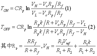
[0025] Such as figure 2 The hysteresis control circuit diagram of the Boost converter of the present invention. Vi is the input voltage, S 1 , S 2 main switching tube, L is the inductance, C is the charging capacitor, co is the filter capacitor, R 1 , R 2 Adjust the resistance for the upper and lower limit thresholds, R f Adjust resistors for feedback, V ref , V rc : reference voltage, R o for the load, R is the branch resistance, R f is the feedback resistor, Vo is the output voltage, V L , V H Low threshold voltage and high threshold voltage for the hysteresis comparator;

[0026] V n is the hysteresis co...


PUM


Abstract

The invention relates to a hysteresis control method of a Boost convertor. Circuit output is connected with the ground through a feedback adjustment resistor and a charging capacitor, a hysteresis comparator is controlled by charging and discharging of the charging capacitor to output a high level and a low level, an output signal of the hysteresis comparator is connected with a drive circuit, output PWM signal frequency is controlled by the drive circuit according to an input signal, so that connection time and disconnection time of a switching tube of the circuit are controlled, and output load voltage is adjusted. According to the hysteresis control method of the Boost convertor, load adjusting capacity is good; an error amplifier is not used, feedback phase delay does not exist, a phase compensation circuit is completely not required, circuit design is simple, and large consumption of manpower and material resources is not needed; when load rise or load drop occurs, good dynamic adjustment can be achieved through small overshoot in short adjustment time; the requirements for input and output high-speed instant response, the small size, low cost and high efficiency of the Boost direct-current convertor are satisfied; the accurate constant frequency characteristic is achieved, the design of electromagnetic compatibility is convenient, and the problem of electromagnetic interference is not prone to generation.

Description

technical field [0001] The invention relates to a DC conversion control method, in particular to a hysteresis control method of a Boost converter. Background technique [0002] The function of the DC-DC converter circuit is to change the DC power into another DC power with a fixed voltage or an adjustable voltage, including a direct DC converter circuit and an indirect DC converter circuit. The direct DC converter circuit is also called a chopper circuit. Its function is to convert the DC power into another DC power with a fixed voltage or an adjustable voltage. There are many types of chopper circuits such as Buck, Boost, and Buck-Boost. The output voltage of the Boost circuit is higher than the input voltage. As a basic DC / DC converter, it has been widely used in various DC boosting occasions such as hybrid electric vehicles, aviation power supplies, and new energy development. With the gradual increase of application occasions, the requirements for the performance index ...

Claims


Application Information

Patent Timeline
IPC IPC(8): H02M1/088H02M3/07
Inventor 赵晋斌刘永晓
Owner SHANGHAI UNIVERSITY OF ELECTRIC POWER
Learn More