Optical engine structure with same substrate

A light engine and substrate technology, applied in the field of lighting, can solve the problems of difficult standardization, poor matching, complicated processes, etc., and achieve the effects of good matching, improved light efficiency, and good thermal conductivity.

Active Publication Date: 2013-10-16
上海晶擎能源科技有限公司
View PDF8 Cites 23 Cited by
  • Summary
  • Abstract
  • Description
  • Claims
  • Application Information

AI Technical Summary

Problems solved by technology

Discrete structure may cause problems of poor matching, poor consistency, difficult standardization and complex process

Method used


Image

  • Optical engine structure with same substrate

Examples


Embodiment 1

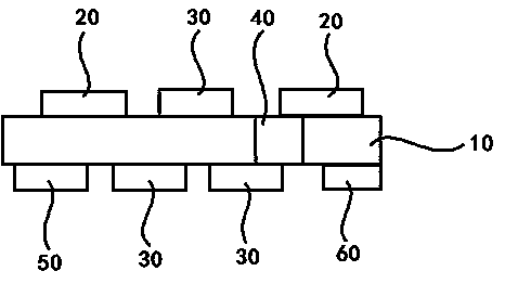
[0022] as attached figure 1 As shown, the same-substrate light engine structure described in Embodiment 1 includes an aluminum or aluminum alloy substrate 10, the substrate includes a first main surface and a second main surface opposite to the first main surface, and the substrate 10 is Integrated with LED light source 20 and LED constant current driver 30, the LED light source is an LED chip or LED lamp bead, and the LED light source 20 and LED constant current driver 30 are arranged on any main surface or on two main surfaces at the same time. On the surface; the LED constant current driver 30 is electrically connected to the LED light source 20; and the LED constant current driver 30 is used to convert the input direct current or alternating current into a steady current, and the steady current is supplied to the LED light source 20, and complete the electro-optic conversion to emit illumination light. The LED light source can be combined on the substrate by means of die ...

Embodiment 2

[0024] Compared with Example 1, the only difference is that a different substrate is used. Moreover, the substrate is a highly thermally conductive insulating printed circuit board; the printed circuit board includes a metal base, a ceramic layer sequentially formed on the metal base, and a metal conductive layer formed on the ceramic layer.

[0025] Preferably, the high thermal conductivity insulating aluminum-based printed circuit board includes a metal aluminum substrate, an aluminum transition layer sequentially formed on the metal aluminum substrate, an AlON ceramic coating formed by an arc ion plating method, and A metal conductive coating formed on a coating. The aluminum-based printed circuit board is prepared by the above method, wherein the step of depositing the aluminum transition layer adopts the following process: the target used is an aluminum sputtering target with a purity of 99.99 wt%, and the background vacuum degree of the vacuum chamber is 5×10 -4 Pa, th...

Embodiment 3

[0027] Compared with Example 1, the only difference is that a different substrate is used. Moreover, the substrate is a highly thermally conductive fluorescent insulating printed circuit board; the printed circuit board includes a metal base, a thermally conductive fluorescent ceramic layer formed sequentially on the metal base, and a metal conductive layer formed on the thermally conductive fluorescent ceramic layer.

[0028] The high thermal conductivity fluorescent insulating printed circuit board includes a fluorescent insulating layer and a metal circuit layer sequentially formed on a metal base. The metal substrate can be metal plates such as Al, Cu, Ag and Ni or their alloy plates; the metal circuit layer is formed by dry or wet etching through the deposited conductive metal layer, and the conductive The metal is generally preferably Cu, Ag, Al or alloy materials thereof. The fluorescent insulating layer can be formed by various known coating methods, for example, it c...


PUM


Abstract

The invention relates to an optical engine structure with a same substrate. The optical engine structure comprises the substrate, wherein LED light sources and LED constant current drivers are integrated on the substrate, and the LED constant current drivers are electrically connected with the LED light sources, and are used for converting the input DC or AC into steady-flow current to be supplied for the LED light sources to enable the LED light sources to emit illumination light after the electro-optical conversion is completed. According to the structure, the LED constant current driver as well as LED chips or lamp beads are integrated on the substrate, forming a standardized design of the LED light sources is facilitated, moreover, the matching of the LED constant current drivers and the LED chips is excellent, stable light source output can be formed, the improvement of the light efficiency can be facilitated, and the structure is excellent in thermal conduction, and has high voltage breakdown resistance performance.

Description

technical field [0001] The invention belongs to the technical field of lighting, and more specifically, the invention relates to a light engine structure with the same substrate for optical devices. Background technique [0002] LED is a new type of solid-state cold light source. It has the advantages of simple structure, light weight, small size, low energy consumption, fast response, good shock resistance and convenient use, so it is favored by people. Under the same illuminance, the power consumption and lifespan of LED lamps have obvious advantages over incandescent lamps and fluorescent lamps. Moreover, LEDs can be used not only as indicator lights, display light sources and signal light sources, but also for general lighting. Therefore, people have formed a consensus that LED is the fourth-generation light source after incandescent lamps, fluorescent lamps and HID lamps, and is recognized as the most promising electric light source in the 21st century. [0003] The m...

Claims


Application Information

Patent Timeline
Patent Type & Authority Applications(China)
IPC IPC(8): F21S2/00F21V23/00F21V19/00H01L25/16F21Y101/02
Inventor 高鞠
Owner 上海晶擎能源科技有限公司
Why Eureka
Try Eureka